3 General Principles
FLUXUS ADM 8027, F801, ADM 8127B
UMFLUXUS_F8V4-6-1EN, 2018-10-10
11
3
General Principles
For the ultrasonic measurement of the flow rate, the flow velocity of the fluid in a pipe is determined. Further physical
quantities (e.g., volumetric flow rate, mass flow rate) are derived from the flow velocity and from additional physical quan-
tities, if necessary.
3.1
Measurement System
The measurement system consists of a transmitter, the ultrasonic transducers with the transducer cables and the pipe on
which the measurement is conducted.
The ultrasonic transducers are mounted on the outside of the pipe. Ultrasonic signals are sent through the fluid and re-
ceived by the transducers. The transmitter controls the measuring cycle, eliminates the disturbance signals and analyzes
the useful signals. The measured values can be displayed, used for calculations and transmitted.
3.2
Measurement Principle
The flow velocity of the fluid is measured in the TransitTime mode using the ultrasonic-transit time difference correlation princi-
ple (see section 3.2.2). If the proportion of gas or solid particles is too high, the transmitter can toggle to the NoiseTrek mode
(see section 3.2.3).
3.2.1
Terms
Flow profile
Distribution of the flow velocities over the cross-sectional pipe area. For an optimal measurement, the flow profile has to
be fully developed and axisymmetrical. The shape of the flow profile depends on whether the flow is laminar or turbulent
and is influenced by the conditions in the supply line of the measuring point (see chapter 5).
Reynolds number Re
Coefficient describing the turbulence behavior of a fluid in the pipe. The Reynolds number Re is calculated from the flow
velocity, the kinematic viscosity of the fluid and the inner pipe diameter.
If the Reynolds number exceeds a critical value (usually approx. 2 300, if the fluid flows in a pipe), a transition from a lam-
inar flow to a turbulent flow takes place.
Laminar flow
A flow without any turbulence. There is no disruption between the parallel flowing layers of the fluid.
Turbulent flow
A flow in which turbulence (swirling of the fluid) occurs. In technical applications, the flow in the pipe is mostly turbulent.
Transition range
The flow is partly laminar and partly turbulent.
Transit time difference
∆
t
Difference of the transit times of the signals. In the TransitTime method, the transit time difference of the signals in and
against the flow direction is measured, in the NoiseTrek mode - the time difference of the signal from the transducer to the
particle and from the particle to the transducer. The flow velocity of the fluid flowing in the pipe is determined from the tran-
sit time difference (see Fig. 3.2, Fig. 3.5 and Fig. 3.4).
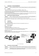
Fig. 3.1: Example of a measurement setup
transducers
transmitter
pipe


