Flexco Novitool Ply 130 Safety And Operation Manual Download Page 1

LISTED

CM

Cert. to CSA 

Std. C22.2 No. 68

5011455

www.flexco.com

www.flexco.com

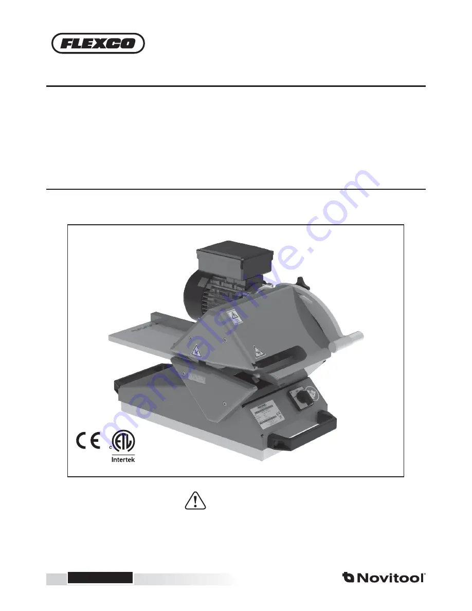
Separate between the plies of a conveyor belt.

IMPROPER OR UNSAFE use of this tool can result in serious bodily injury! This manual contains important information 

about product function and safety. Please read and understand this manual BEFORE operating the tool. Please keep this 

manual available for other users and owners before they use the tool. This manual should be stored in a safe place.

WARNING

Novitool

®

 Ply 130

 Separator  

Workbench & Optional Workshop Cart  

Safety and Operation Manual

Summary of Contents for Novitool Ply 130

Page 1: ...odily injury This manual contains important information about product function and safety Please read and understand this manual BEFORE operating the tool Please keep this manual available for other u...

Page 2: ...rance as Necessary 25 Parts Lists 34 Electrical Schematics 35 Technical Assistance 40 WEEE 41 EU Declaration 42 Disclaimer The Ply 130 ply separator has been tested successfully with different belt ty...

Page 3: ...ain Components Ply 130 1 Adjuster handle 2 Finger guard 3 Upper traction roller 4 Ply separation blade 5 Lower traction roller 6 Electric motor 7 Adjustable guide 8 Infeed table 9 Operating switch 10...

Page 4: ...an be used to prepare finger over finger splices and stepped splices With the adjuster handle you determine the depth to split the belt It may be possible to split between every ply of the belt and in...

Page 5: ...Power tools create sparks which may ignite the dust or fumes CAUTION Keep bystanders children and visitors away while operating a power tool Distractions can cause you to lose control WARNING Never le...

Page 6: ...o not abuse the cord Never use the cord to carry the tool or pull the plug from a receptacle Keep cord away from heat oil sharp edges or moving parts Replace damaged cords immediately Damaged cords in...

Page 7: ...efore opening servicing the machine CAUTION When servicing a tool use only identical replace ment parts Use of unauthorized parts or failure to follow Maintenance Instruction may create a risk of elec...

Page 8: ...om the feeding rolls and splitting area Always guide the material in a way that your hands have a minimum distance of 10 cm 3 94 from this area CAUTION Do not use dull or damaged blades knives 7 PLY C...

Page 9: ...B1 A Workbench Installation A1 The Ply 130 must for safety reasons be mounted on a firm and level workbench Fasten four bolts M8 x 16 mm table thickness in threaded holes located in bottom of ply tra...

Page 10: ...08233 oriented as shown in above illustration and reinstall handles Retrofit Tray For serial numbers starting with 20xxxxxx the ply tray must be replaced with retrofit Ply 130 tray item 08233 Serial...

Page 11: ...11 B CartAssembly A B C 2x Fixed casters with brake Bottom View Caster Keys Swivel caster Swivel caster with brake Bolt M10x25 M10 Nylok flanged 1x 1x 16x Bolt M8x20 4x 16x A B C B1 B3...

Page 12: ...eels For position and materials refer to drawing on page 11 Ensure key tabs on cart base engage with caster key features A For access to Ply 130 mounting bolt hole positions A remove drawer by pushing...

Page 13: ...ly 130 onto cart with motor A toward the logo side B Mount Ply 130 on support deck Ensure four bolt holes on tray line up with four bolt holes on top deck Tighten M8x20 bolts included with Ply 130 Car...

Page 14: ...o com 14 www flexco com B1 B1 B9 B8 1 2 For moving cart 1 Place foot switch in cart 2 Hang power cord on cart Reinstall drawer by engaging the drawer slides on both sides of cart 14 Ply 130 Cart Insta...

Page 15: ...a splice the material is separated between the belt plies The depth of separation should be determined by the operator since it will depend on belt material number of plies and splice type Under infe...

Page 16: ...e lower traction roller Lock in position Note Scale is for reference only and not a linear dimension Set operating switch to FORWARD Caution When toggling to REVERSE traction rollers are immediately p...

Page 17: ...ts it is recommended to separate trailing corner as shown in photo to prepare sample for full width ply separation Feed belt material through Ply 130 Set operating switch to OFF when separation is com...

Page 18: ...nance Measure and Adjust Blade Roller Clearance as Necessary Lock the adjuster handle to the minimum 0 position Place a sample piece of belt cover side down onto the belt support tray Run belt through...

Page 19: ...19 Once foil film setting is acceptable run foil film as needed Separating to Make Foil Film B1 D3...

Page 20: ...co blade calibration jig and clearance shims are readily available The operator is wearing cut proof safety gloves and safety glasses Release blade by unscrewing two bolts at bottom of blade with a 5...

Page 21: ...de Replacement Lock adjusting handle in position 4 0 to 4 5 B1 F3b E3 Place calibration jig on feed table with thin edge toward rollers Plug in power connection Turn switch to FORWARD B1 E5 B1 E4 Lock...

Page 22: ...taneously turning on Ply with foot switch When lip of jig is tight up against the Ply frame release the foot switch and toggle operating switch to OFF Disconnect power Note Calibration jig must be par...

Page 23: ...lade edge B1 E7 Ensure brass spacers are pres ent either in the Ply frame or on bolt Finger tighten bolts only so that the blade can still shift long bolt in rear and short bolt in front Note Bolts do...

Page 24: ...lade so that the blade tip squarely rests against the calibration jig E9 Reconnect power cable to electrical power supply Rotate switch to REVERSE to release calibration jig from between traction roll...

Page 25: ...ance between the upper traction roller and top of blade begin by positioning the adjustment handle to 0 Insert the white thickness clearance shim between the ply separation blade and the top traction...

Page 26: ...e Measure and Adjust Blade Roller Clearance As Necessary If adjustment is needed unscrew clamp nut on adjustment guard plate F2 F3 F4 Using a 5 mm hex key remove the handle For easier removal of motor...

Page 27: ...r Clearance As Necessary Remove the electric motor to gain sufficient access for adjustment of traction rollers by first removing the torque arm bolt using a 6 mm hex wrench F5 F6 F7 Slide motor off s...

Page 28: ...ler Clearance As Necessary F8 F9 Carefully rest motor on infeed tray Caution Do not allow motor to slide off of tray surface For upper roller adjustment loosen and remove gas spring fixation screw Adj...

Page 29: ...A clockwise one quar ter turn or until moderately tight To decrease the clearance between the top roller and blade loosen screw A counterclockwise one quarter of a turn and tighten screw B clockwise o...

Page 30: ...little resistance as the operator slides the white shim between the top traction roller and blade and the black shim should not pass through between the top traction roller and the blade Repeat steps...

Page 31: ...and tighten screw C clockwise one quarter turn or until moderately tight B1 Lock the adjusting handle back to 0 Check for clearance between the blade and lower traction roller by inserting the clearan...

Page 32: ...intenance Measure and Adjust Blade Roller Clearance As Necessary Then reinstall the clamp nut F19 Reinstall motor Align shaft key with key slot F20 F18 Once adjustments have been made reinstall the gu...

Page 33: ...ade Roller Clearance As Necessary Reassemble the motor to the frame placing the spacer between the motor torque arm and ply base Insert 8 mm hex bolt with washer and tighten G12e Note Ensure rubber gr...

Page 34: ...0 AMP 08837 FUSE 10 AMP 08838 FUSE 15 AMP 08839 TRANSFORMER PLY130 115 230 24 08840 TRANSFORMER PLY130 230 460 24 08841 REVERSE CONTACTOR KIT 1PH Ply 130 Step Cutter Ordering Information Low Volume Hi...

Page 35: ...35 H Electrical Schematics 08802...

Page 36: ...www flexco com 36 www flexco com Electrical Schematics 08803 08...

Page 37: ...37 Electrical Schematics 08809 12 08834...

Page 38: ...www flexco com 38 www flexco com Electrical Schematics 08800 08832 33...

Page 39: ...39 Electrical Schematics 08801...

Page 40: ...www flexco com 40 www flexco com I Technical Assistance Contact Flexco s Customer Service if technical assistance or repair is needed www flexco com...

Page 41: ...s WEEE compliance very seriously This equipment is intended to be repairable in foreseeable circumstances Should product disposal be required contact Flexco Europe at 011 49 7428 9406 0 or Flexco UK a...

Page 42: ...www flexco com 42 www flexco com K Declarations...

Page 43: ......

Page 44: ...1 Woodlands Spectrum I Singapore 738068 Tel 65 6484 1533 Fax 65 6484 1531 E mail asiasales flexco com Visit www flexco com for other Flexco locations and products 2018 Flexible Steel Lacing Company 09...

Reviews: