FTS 371 SMART USER MANUAL
Flash Technology, LLC
Revision 4 – 9/7/2021
17
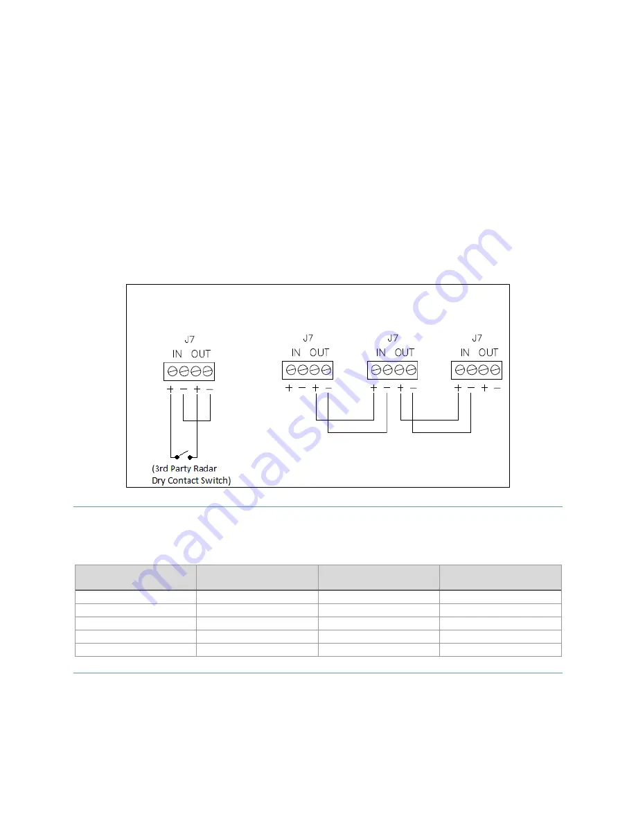
When the RADAR configuration switch is placed in the ON position, an external device such as a radar system may
inhibit the output of the beacon. Wire the dry contact from the external device to connector J7 terminals with IN+
and OUT+ as shown below and jumper the terminals IN- to OUT-. The fail-safe design requires a closed contact to
inhibit the output of the beacon so the beacon is on if the contact is open and off if closed.
For primary/secondary synchronization, set the RADAR configuration switch to the OFF position and wire the J7
SYNC connector to other controllers as shown below, primary OUT+ and OUT- to secondary #1 IN+ and secondary
#1 IN-, etc. Each secondary must have its secondary configuration dipswitch set to ON and its flash configuration
set to match the primary: flash type (efficiency/legacy), flash spec (FAA/ICAO) and beacon and marker
flashing/steady. Secondary units with nonmatching configuration will not flash in unison with the system. A
photodiode is connected to the primary controller only, not the secondary unit.
Note:
The EXT SYNC LED is on at the beginning of SYNC pulse and off at end of SYNC pulse on both primary and
secondary. The secondary’s EXT SYNC LED will flash ON only if properly wired to primary so is a good
troubleshooting check.
CATENARY OPERATION
For catenary operation, wire the systems as shown above and set the configuration switches as in the table below.
Note that for the Middle level, both CAT T and CAT B switches should be set to OFF.
Primary (CAT TOP)
Secondary #1 (CAT MID)
Secondary #2 (CAT BOT)
SECONDARY
OFF
ON
ON
RADAR
OFF
OFF
OFF
60FPM
ON
ON
ON
CAT T
ON
OFF
OFF
CAT B
OFF
OFF
ON
GPS SYNCHRONIZATION
For GPS synchronization, the optional GPS Sync Kit must be installed including external GPS antenna mounting.
Refer to the FTS 371 GPS Sync Kit (P/N 1370285) Installation Instructions for details.
The portion outlined in red shows the location of the FTS 371 GPS OPTION PCB PN 2433000 on the controller PCB.
Primary Dry Contact
Radar Input
Primary and Secondary Synchronization
Primary
Secondary #1
Secondary #2


