Page 16
Copyright
2008 FiveFish Studios
www.fivefishstudios.com
SC-1mk2 Microphone Preamp Kit
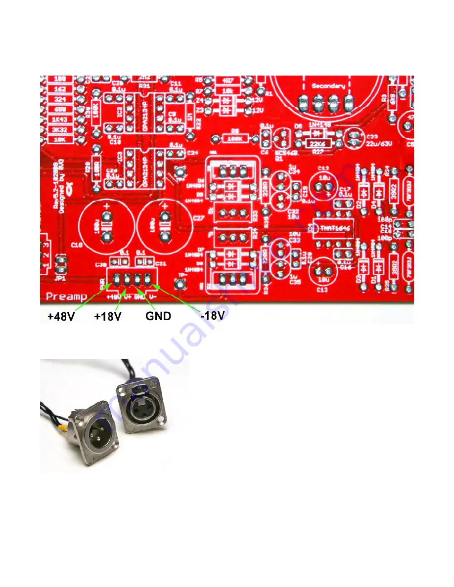
STEP 16: Solder wires to the +48V, V+, GND, and V- pads. Connect the wires to your power supply (or PSU-1848/2448 If you
also bought the PSU kit). All pads are 0.1” pitch on center, so you can use standard Molex 0.1” headers and connectors with the
SC-1mk2 board.
STEP 17: Solder XLR Jacks to the PCB using hookup wires. Solder pads 1, 2 and 3 to XLR Pins 1, 2 and 3 respectively. Do the
same procedure for both the input XLR and output XLR jacks. All pads are 0.1” pitch on center, so you can use standard Molex
0.1” headers and connectors with the SC-1mk2 board.
PAD 1 = XLR Pin 1 = GROUND
PAD 2 = XLR Pin 2 = HOT
PAD 3 = XLR Pin 3 = COLD


