11 / 28
FMod-IPECMOT 48/10 User Manual v2.5
This bus can display a video resolution up to 1920x1080px30fps.
LVDS Screen
LVDS screen must be connected to the media player with a custom cable.
There is no standard cable for LVDS, each screen must have its specific
cable.
With this media player you can connect LVDS screen which have one or
two LVDS channel and a color depth of 18bit or 24bit.
It can also power a screen backlight and control it by sending control signals
(enable, pwm) or directly control the current to power the backlight.
This bus can display a video resolution up to 1920x1080px60fps.
LVDS Connector
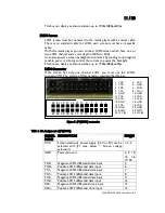
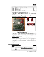
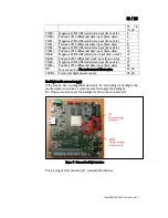
If the screen has only one channel LVDS, you must use the LVDS1
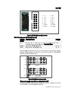
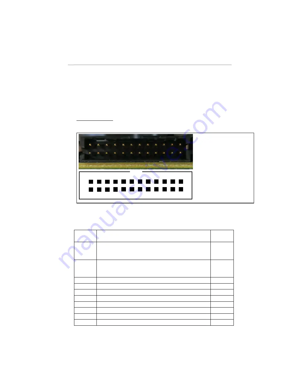
connector (J7). The pinning of this connector was described below:
Figure 5 : J7 (LVDS1) connector
Table 1 : Pin Assignment of J7 (LVDS1)
SIGNAL
NAME
DESCRIPTION
PIN(s)#
VCC
Screen electronic power supply (3.3V or 5V) can be
selected with JP1 (see below “: Screen voltage
selection”)
1, 2, 3
GND
Power Ground
4, 9, 10,
15,
16,
19, 20
TX0-
Negative LVDS differential data input
5
TX0+
Positive LVDS differential data input
6
TX1-
Negative LVDS differential data input
7
TX1+
Positive LVDS differential data input
8
TX2-
Negative LVDS differential data input
11
TX2+
Positive LVDS differential data input
12
CLK-
Negative LVDS differential clock input
13
CLK+
Positive LVDS differential clock input
13
1. VCC
2. VCC
3. VCC
4. GND
5. TX0-
6. TX0+
7. TX1-
8. TX1+
9. GND
10. GND
11. TX2-
12. TX2+
13. CLK-
14. CLK+
15. GND
16. GND
17. TX3-
18. TX3+
19. GND
20. GND
21. BL EN
22. PWM
23. 12V BL
24. 12V BL
23 21 19 17 15 13 11 9 7 5 3 1
24 22 20 18 16 14 12 10 8 6 4 2


