


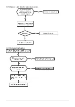

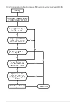


9.3.3.4 Outdoor unit fan speed has been out of control (E8)
Index 1:
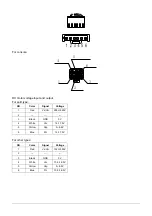
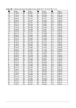
1. Outdoor DC fan motor(control chip is inside fan motor)
Power on and when the unit is in standby, measure the voltage of pin1-pin3, pin4-pin3 in fan motor
connector. If the value of the voltage is not in the range showing in below table, the PCB must have
problems and need to be replaced.
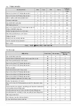
DC motor voltage input and output
NO. Color
Signal
Voltage
1 Red
Vs/Vm
140V~380V
2 --- --- ---
3 Black
GND 0V
4 White Vcc
13.5-16.5V
5 Yellow Vsp 0~6.5V
6 Blue FG 15V
Summary of Contents for FS2MIF-141AE2
Page 8: ...5 Wiring diagram FS2MIF 141AE2 FS2MIF 181AE2 FS3MIF 211AE2 FS3MIF 271AE2 8 ...
Page 9: ...FS4MIF 281AE2 FS4MIF 361AE2 9 ...
Page 10: ...FS5MIF 421AE0 10 ...
Page 33: ...9 3 1 2 Indoor outdoor units communication error ...
Page 41: ...9 3 3 2 Communication malfunction between IPM board and outdoor main board ODU E3 ...
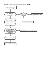
Page 44: ...9 3 3 5 High pressure protection ODU P1 For FS4MIF 281AE2 FS4MIF 361AE2 FS5MIF 421AE0 ...
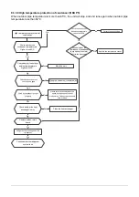
Page 46: ...9 3 3 7 Current protection of compressor ODU P3 ...


