


C1 Controllers and Transmitters
Instruction Manual
September 2009
30
7. Attach the replacement relay and new relay
gasket with machine screws inserted through the
back of the case. Reinstall the output or supply
gauge.
8. Connect the tubing, and check all connections for
leaks. Perform the appropriate calibration
procedures.
Changing Output Signal Range
Use the following information and subsequent
procedures when changing the output signal range
of the controller or transmitter. Use the following
procedure:
D
For a controller or transmitter, use this
procedure to change from a 0.2 to 1.0 bar (3 to 15
psig) to a 0.4 to 2.0 bar (6 to 30 psig) output signal
range or vice versa.
D
For a differential gap controller, use this
procedure to change from a 0 and 1.4 bar (0 and 20
psig) to a 0 and 2.4 bar (0 and 35 psig) output signal
range or vice versa.
D
When changing the supply pressure source to
a new range, refer to table 5 for supply pressure
requirements for the output signal range selected.
Also, make appropriate changes to the nameplate of
the controller or transmitter, reflecting the new range
selections. Refer to figure 23 or 24 for key number
locations unless otherwise directed.
1. Shut off the supply pressure and process lines to
the controller or transmitter.
2. Disconnect the tubing from the mounting base
(key 57) and calibration adjuster (key 36).
Disconnect the tubing that connects the pressure
block (key 10, figure 21 or 22) to the Bourdon tube
or bellows assembly (key 5 or 52), at the pressure
block end.
3. Unscrew the machine screws (key 41, figure 21
or 22), and remove the subassembly from the case.
4. If the controller or transmitter uses a Bourdon
tube sensing element disconnect the Bourdon tube
from the beam (key 39) by removing the screw
(key 56). Be careful to avoid losing the bearing
(key 31). Unscrew the machine screws (key 55)
and remove the washers and Bourdon tube (keys 45
and 5).
5. Unscrew the bellows screws (key 53) from each
end of the mounting base (key 57).
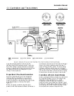
O
−
RING
(KEY 77)
A6281
−
1 / IL
Figure 20. Bellows Screw Detail
Note
The bellows screws (key 53) have an
O
−
ring (key 77, figure 20) installed
beneath the bellows screw head.
Remove the O
−
ring and obtain a
replacement when re
−
assembling the
bellows.
6. Unscrew the spring adjustor (key 65). Unclip the
lock spring (key 72, figure 18) and remove the
indicator scale (key 69) and the proportional band
adjustment knob (key 73).
7. Compress the bellows (key 52) so that the end of
the bellows, beam (key 39), and cantilever spring
(key 8) can be removed from the mounting base
(key 57).
8. Unscrew the bellows (key 52) from the
bellows/cantilever assembly.
9. Remove the cantilever spring from the spacer
(key 34).
a. Remove the beam machine screws (figure 19,
step 4).
b. Remove the cantilever machine screws
(figure 19, step 3).
c. Remove the inner flexure (figure 19, step 1)
and install it on the new cantilever.
10. Install the new cantilever spring (key 8) and
reconnect the beam (key 39) to the bellows spacer
(key 34) in reverse sequence of steps 9a. and 9b.
and reattach the bellows to the beam/cantilever
assembly.
11. Compress the bellows and install them into the
mounting base (key 57). Align the cantilever spring
with the gain adjustment bar (key 63). Install the
indicator scale (key 69) and the proportional band


