


Type 9500
7
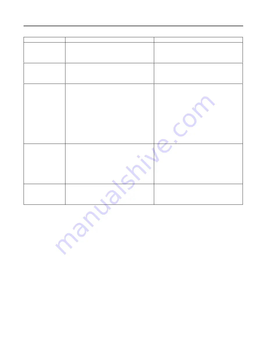
Table 3. Troubleshooting Guide
Fault
Possible Cause
Correction
1. Leakage out sides of
valve (at thrust plates)
between thrust bushings
and shaft.
a. Hub seals require adjustment.
b. Taper pins are not sealed.
a. Adjust using Hub Seals portion of Adjustments
procedures.
b. Remove valve from line and re-seat taper pins or install
new taper pins using Maintenance procedures.
2. Leakage out sides of
valve (at thrust plates)
between valve body and
thrust bushings, leakage
at flanges, faces, or both
a. Flange gaskets used.
b. Partial O-ring bead on liner faces damaged.
a. Check to see if flange gaskets are being used; if so,
remove gaskets.
b. Replace liner using Maintenance procedures.
3. Leakage through
disk/liner seal
a. Hub seals require adjustment.
b. Linkage requires adjustment.
c. Actuator has insufficient torque output to close disk
against pressure drop. (Actuators are selected to have
sufficient torque output to shut off the flow against a
specific pressure drop, not necessarily against the
maximum allowable pressure drop. Be sure that the
pressure drop for which the actuator is selected is not
being exceeded.)
d. Liner has been damaged by flowing medium or other
valve parts damaged by being subjected to service
conditions beyond those for which valve is designed.
a. Adjust seals using Hub Seals portion of Adjustments
procedures.
b. Refer to Linkage portion of Adjustments procedures.
c. If possible, check shutoff at lower pressure drops. If
shutoff is obtained at low pressure drops, but actuator
stalls and does not produce full disk rotation at service
pressure drop, actuator output torque is too low. For piston
actuators, it may be possible to increase output torque by
increasing supply pressure. Do not exceed maximum
allowable supply pressure of actuator.
d. Inspect and replace parts using Maintenance
procedures.
4. Valve shaft will not
rotate
a. If actuator does not stall, but shaft does not rotate, the
spline teeth on the valve shaft are sheared.
b. If actuator stalls, shaft is binding in bushings due to
linkage misalignment caused by excessive wear of linkage
parts.
c. If actuator stalls and linkage is not misaligned, actuator
may have insufficient output torque to rotate disk against
flow.
a. Refer to the actuator instruction manual to remove
actuator cover plate. Replace valve shaft using
Maintenance procedures if spline teeth are sheared.
b. Replace linkage parts.
c. Check actuator operation with no pressure applied to the
valve. If valve now functions properly, actuator is too
small.
5. Valve shaft rotates, bur
valve does not control
process fluid
Taper pins (or drive shaft spline for coated-disk
constructions) have been sheared due to obstruction to
disk rotation or other internal parts damaged by being
subjected to service conditions beyond those for which the
valve was designed..
Inspect and replace parts using the Maintenance
procedures.
7. Remove disk from valve body.
8. Remove liner (key 2) from valve body.
Some Type 9500 valves have the liner bonded to the
valve body. If the valve has a bonded liner, burn or
chip out the liner.
To strip the liner out with solvent, use Eccostrip 57,
Houghto Clean 224, or equivalent solvent. Cover the
valve with solvent bath or enclose the solvent bath
around the liner. Remove all adhesive after the liner
has been removed.
Reassembly
Before reassembling the valve, clean and inspect all
parts. Key number locations are shown if figure 7. Refer
to the
Parts List section to obtain replacement parts.
1. Insert liner (key 2) into valve body. A small amount
of silicone grease applied to the outside surface of the
liner will aid insertion of the liner. However, do not use
grease if the valve is to be used for oxygen service.
In vacuum service applications, upon customer re-
quest, you may use Eccobond 285/24LV bonding
agent (part no. G1414006992) to bond the liner to the
valve. Though bonding is not required use the lettered
steps below when bonding the liner to the valve body .
If a different agent is to be used, follow instructions
furnished by the bonding agent manufacturer. In ab-
sence of instructions, consult your Fisher Controls
sales office or sales representative.
a. Roughen bonding surface of liner with a stiff
wire brush. De-grease bonding surfaces of liner
and valve body with solvent.
b. Mix the two epoxy components thoroughly and
spread a thin coat [approximately 0.015 inches