1-3
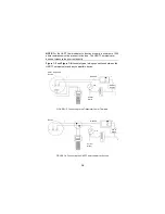
NOTE: For the HART Communicator to function properly, a minimum of 250
ohms resistance must be present in the loop. The HART Communicator
does not measure loop current directly.
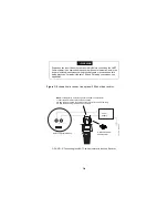
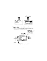
Figure 1-3 and Figure 1-4 illustrate typical wiring connections between the
HART Communicator and any compatible device.
FIGURE 1-3. Connecting to the Transmitter Comm Terminals.
FIGURE 1-4. Connecting the HART Communicator to the Loop.
R
L
≥
250
Ω
Power
Supply
+
_
+
_
_
+
mA
+
_
+
_
Current
Meter
+
_
HART-compatible
Device
_
+
Power
Supply
_
+
+
_
Current
Meter
_
+
R
L
≥
250
Ω
_
+
_
+
Device
mA
Summary of Contents for HART 275
Page 48: ...1 40 ...
Page 56: ...2 8 ...
Page 94: ...3 38 ...
Page 106: ...B 6 ...
Page 114: ...D 4 ...


