517804 D
26
5 DIAGNOSTIC
MODES
5.1 Diagnostic
Mode
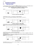
To enter diagnostic modes, press and hold the
MENU
and
UP
button for 4 seconds. The first display shown is
the PC temperature as shown in Diagram A. The actual temperature of the PC is shown.
Note:- Temperatures shown on display are in Degrees Centigrade
(Temperature Conversion Table on last page)
Diagram A
PC Sensor Temperature is 4
°
C (39.2
°
F).
Press
UP
button once more – FC temperature is indicated Diagram B
Note: 12.0 min shown, indicates the temperature of the FC sensor is -12º C (53.6
°
F)
Diagram B
FC Sensor Temperature -12
°
C (53.6
°
F)
Press
UP
button once more – Defrost sensor temperature is indicated Diagram C.
Note: 18.0 min shown, indicates the temperature of the Defrost sensor is -18º C (0.0
°
F)
Diagram C
Defrost Sensor Temperature -18
°
C (0.0
°
F)
Press
UP
button once more – Input/Output status Diagram D
IO
shown indicates the product is in input/output status. The LCD that are highlighted indicates what
components are on.
Note: When the PC door is opened the backlight will turn off. The LCD for the FC or PC door will come
on when either door are opened.
Diagram D
Input/Output Status
Press
UP
button once more – Spare. The LCD will display 87.5, which is the software maximum temperature
and is not in use for this product.


