background image

517804 D 

25 


4.7 

Testing Icemaker Motor 

Testing of the icemaker motor is carried out at the power module.  

Note: Before any testing is carried out ensure the product has an ice bin in place and the icemaker arm 
is in the down position. 

Procedure: 

• 

Disconnect the refrigerator from the power supply. 

• 

Remove the power module to expose connectors. 

• 

Remove the connector from the Icemaker PCB. 

• 

Check the resistance of the motor between pins 5 & 6 – Resistance should be 35

Ω

 +/- 5%. 

• 

Check the tact switch continuity between pins 4 & 7 – The switch should be closed. 


Note: To identify pin numbering, Pin 10 and 11 are White wires 


4.8 

Water Valve Testing 

The water valves are located in the unit compartment. 

• 

Disconnect the refrigerator from the power supply. 

• 

Remove the connector from the valve. 

• 

Resistance of the water valves is 14 

± 5% 

 
When testing for voltage at the ice or water valve: 

• 

Disconnect the refrigerator from the power supply. 

• 

Remove the connector from the water valve. 

• 

Place meter probes into the connector of the valve that is faulty (ice valve or water dispenser valve). 

• 

Reconnect the refrigerator to the power supply. 

• 

Place a glass into the dispenser to operate the valve (for water dispenser valve only). 

• 

Place the product into a forced harvest (for icemaker only). 

 
The voltage at the connector (once disconnected from the valve) should be 12 volts DC.  Care should be taken 
not to damage the connector or wiring. 


4.9 

Testing of flow Meter (Products before January 2009) 

The flow meter cannot be tested electrically.  If a fault occurs where the flow meter is suspected to be faulty, 
the Flow Meter Calibration procedure (refer to Section 0 Flow Meter Calibration) is to be followed, and if after 
the procedure has been followed the fault still exists, replace the flow meter. 

Motor - Pins 5 & 6 

Tact switch continuity –  

Pins 4 & 7 

Pins 10 & 11 

Summary of Contents for E522BLXFDU

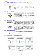
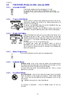
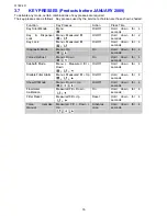
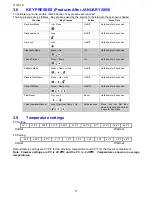
Page 1: ...Service Manual ACTIVE SMART Refrigerator Freezer Ice And Water Models E522BRXFDU E522BRXU E522BLXFDU E522BLXU PRODUCT CODES 22128 22179 22129 22184 22272 22273 22296 22297 SERVICE SUPPLEMENT 517804 D...

Page 2: ......

Page 3: ...ARCH 2009 The specifications and servicing procedures outlined in this manual are subject to change without notice The latest version is indicated by the reprint date and replaces any earlier editions...

Page 4: ...517804D 4 FISHER PAYKEL ACTIVE SMART ICE AND WATER Fisher Paykel Appliances 5800 Skylab Road Huntington Beach CA 92647 Telephone 888 936 7872 COPYRIGHT FISHER PAYKEL LTD 2007 ALL RIGHTS RESERVED...

Page 5: ...Mode 13 2 6 4 Water Dispensing 13 2 6 6 Sabbath Mode 13 2 6 7 Key Silent Mode 14 2 6 8 Dispense Lock 14 2 6 9 Key Lock 14 3 ICEMAKER 14 3 1 Ice Production 14 3 2 Information About The Icemaker 14 3 3...

Page 6: ...PROBLEM SOLVING CHECKLIST 33 9 SERVICE PROCEDURES 34 9 1 Component Replacement 34 9 1 1 Icemaker PCB Replacement 34 9 1 2 Icemaker Unit Replacement 34 9 1 3 Refitting Icemaker 34 9 1 4 Icemaker Temper...

Page 7: ...sing through a 12 volt water valve 3 External Water Filter An external in line water filter is to be fitted to each Ice and Water refrigerator which will come standard with every Ice Water product 4 A...

Page 8: ...enable disable Key lock Water dispenser key lock Filter replacement alert No water alert Fault alert Diagnostics Temperature set points Measured fill calibration 2 2 Display Interface Features Product...

Page 9: ...ured Fill The MEASURED FILL key enables you to select the amount of water to be dispensed Menu The MENU key allows you to scroll through the main menu options Chill Temperature Ice and Settings Arrow...

Page 10: ...2009 Menu The MENU key allows you to scroll through the main menu options Chill Temperature Ice and Settings Arrow Keys The arrow keys are used to scroll through the settings of each function Lock Th...

Page 11: ...y use the MENU key and scroll to CHILL Press the DOWN key until the icon disappears 2 5 3 Bottle Chill Mode Bottle Chill allows the customer to put a bottle in the freezer for a designated amount of t...

Page 12: ...Faults Bottle chill the door will still alarm when the refrigerator is set on key silent mode Indicates the product is in Key Silent Mode To activate or deactivate hold the MENU key for four 4 second...

Page 13: ...omer to take the bottle out of the FC The Freezer automatically changes to it s lowest set point The times are 10 15 20 25 and 30 minutes To activate this mode use the MENU button to scroll to FREEZER...

Page 14: ...around the icemaker will not operate 3 2 Information About The Icemaker The temperature of the FC needs to reach 14 F before the icemaker commences to operate When first switched on the icemaker carr...

Page 15: ...e harvest can continue If the icemaker senses the bin is full the motor resumes its normal position 20 minutes later the testing sequence commences until such time as the ice level is reduced by usage...

Page 16: ...conds Key Lock Menu Measured fill On Off Hold down for 4 seconds Diagnostic Mode Menu Up On Hold down for 4 seconds Forced Defrost Menu Down On Hold down for 4 seconds Sabbath Mode Menu Measured fill...

Page 17: ...isable Filter Alarm Menu Up Lock On Off Hold down for 4 seconds Show Off Mode Menu Down Up On Off Hold down for 4 seconds Filter Reset Up Lock Reset Hold down for 4 seconds Force Icemaker Manual Lock...

Page 18: ...517804 D 18 3 10 Airflow...

Page 19: ...on The previous 2 defrosts were aborted after 30 minutes Primary Action Check defrost element assembly in the FC If faulty replace Fault Code 3 Reason The resistance of all the temperature sensors is...

Page 20: ...fan LAH RAST connector Tertiary Action Replace control module Fault Code 12 Reason The current measured for the ambient heater PC fan and FC fan is higher than expected Primary Action Check the 6 way...

Page 21: ...heater If open circuit replace the heater Fault Code 21 Reason Flapper heater current is high Primary action Check for short circuit of the heater If faulty replace the heater Fault Code 22 Reason The...

Page 22: ...water Fault code 32 will be displayed to make the customer aware of the fault Primary Action Check the solenoid resistance If not within limits replace the solenoid If OK replace the display module i...

Page 23: ...33 Solenoid Driver 2 transistor has failed F34 Both Solenoid Drivers have failed Additional fault codes have been added to the display module in order to detect water leaks or continual flow of water...

Page 24: ...ctor from the icemaker PCB The two white wires Between Pin 10 Pin 11 at the end of the RAST connectors are the sensor wires Testing of the sensor should be in a known stable temperature such as a glas...

Page 25: ...14 5 When testing for voltage at the ice or water valve Disconnect the refrigerator from the power supply Remove the connector from the water valve Place meter probes into the connector of the valve t...

Page 26: ...6 F Diagram B FC Sensor Temperature 12 C 53 6 F Press UP button once more Defrost sensor temperature is indicated Diagram C Note 18 0 min shown indicates the temperature of the Defrost sensor is 18 C...

Page 27: ...efault display after 5 minutes Note The door alarms do not operate when the appliance is in diagnostic mode 5 2 Input Output Status To enter input output status Press and hold the MENU button then pre...

Page 28: ...5 To manually Force a Harvest Products before January 2009 Press and hold down the MEASURED FILL UP DOWN buttons for 4 seconds This will activate the icemaker Note if the bins are removed to observe...

Page 29: ...d to dispense water Water can be dispensed using a measured fill option on the display or free flow The display will light up and the water fill icon will appear when the water is dispensed The dispen...

Page 30: ...the filter has an auto cut out for the water there is no need to turn the water off Grasp and firmly twist the cartridge in an anticlockwise direction to the left when installed in the recommended or...

Page 31: ...sable the alarm if no filter is to be fitted Press and hold the MENU UP LOCK buttons for 4 seconds to turn this feature on off 6 12 Noises Ice and water into the Active Smart products introduced some...

Page 32: ...517804 D 32 7 WIRING DIAGRAMS...

Page 33: ...Door may have been left ajar Check door closing to identify any potential causes Gasket sticking door closing hook Freezer compartment too warm Check PC and FC settings Check temperature of FC and do...

Page 34: ...th front and rear clips should have dislodged If only the rear clip has dislodged place fingers in the front of the icemaker and once again briskly pull the icemaker down Disconnect the icemaker harne...

Page 35: ...to the back wall of the unit compartment Refit in reverse order 9 6 Display Module Replacement The display module is located on the front of the door To remove the module Step 1 Disconnect the refrig...

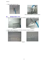
Page 36: ...ad ensure the retaining clip is as shown Refit in reverse to above procedure 9 8 Removing Water Tank Turn the water off at source Remove all shelves Remove the PC duct cover and PC Sensor from duct co...

Page 37: ...ank is removed 9 9 Refitting Water Tank Place the bottom section of the tank onto protrusion on PC liner Refer Diagram C and D Diagram C Diagram D Push the tank towards the rear of the liner until top...

Page 38: ...PC Door Manufactured after May 2007 1 Disconnect the refrigerator from the power supply 2 Remove the top hinge cover to expose the wiring and water tubing 3 Disconnect the edge connector 4 Remove the...

Page 39: ...ore May 2007 Without John Guest fitting under top hinge cover Turn the power off to the refrigerator Turn off water if connected Remove the hinge cover Disconnect the RAST connector Remove the top hin...

Page 40: ...quired to pull the harness through the conduit Ease bullet into conduit and draw harness out of door Once the harness is removed from the door remove the old door from the cabinet 9 12 Fitting a new d...

Page 41: ...te by connecting the harnesses makes the measuring easier Using the bullet place the RAST connector and hose as shown Feed the harness and hose through the door conduit Fit the hose to the Flow Meter...

Page 42: ...nsure water tubes are clipped into position correctly Flow meter wiring is fitted behind flow meter to display panel is correctly fitted Refit LCD housing ensuring wiring harness is firmly in the is n...

Page 43: ...it screw to hinge plate Fit hinge cover Note If the original water tube is to be refitted check the end of the tube for any damage and if the tube has small pieces of plastic protruding cut inch of tu...

Page 44: ...ration Metallic Taste Where the water or ice cubes are discoloured they should not be used If the water is a greenish blue colour the reason for this happening is copper oxide This is not a common fau...

Page 45: ...22 7 6 8 46 4 38 100 4 21 5 8 9 48 2 39 102 2 20 4 10 50 40 104 19 2 2 11 51 8 41 105 8 18 0 0 12 53 6 42 107 6 17 1 4 13 55 4 43 109 4 16 3 2 14 57 2 4 111 2 15 5 15 59 45 113 14 6 8 16 60 8 46 114...

Reviews: