FISCHER Mess- und Regeltechnik GmbH
Product and functional description | 2
BA_EN_MA15_ATEX
9 / 36
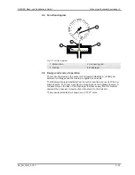
2.4 Function diagram
1
2
3
4
Fig. 4:
Function diagram
1 Motion train
2 Connecting rod
3 Flange
4 Diaphragm
2.5 Design and mode of operation
The measuring element, the concentric corrugated diaphragm, is clamped
between two flanges and the medium is applied on one side.
The diaphragm bulges elastically from its normal position as a result of the ap-
plied pressure. The linear movement is proportional to the applied pressure. A
rod assembly on the side of the diaphragm that faces away from the medium
captures the expansion movement and transfers it to the indicator.
The measurement display is shown on a 270 W° scale.


