FISCHER Mess- und Regeltechnik GmbH
Commissioning | 4
BA_EN_MA15_ATEX
17 / 36
4 Commissioning
4.1 General
All electrical supply, operating and measuring lines, and the pressure connec-
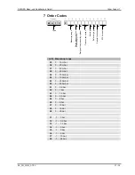
tions must have been correctly installed before commissioning. All supply lines
are arranged so that there are no mechanical forces acting on the device.
Check that the pressure connections do not leak before commissioning.
4.2 Zero point correction
The pressure measuring units are set in the factory before delivery so that they
do not usually need to be adjusted at the assembly site.
The zero-point may need to be corrected for some units on site (see order
code).
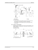
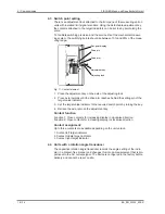
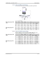
Units with setting screw
Venting valve
Venting valve
Zero-point correction screw
Fig. 9:
Zero point correction
1. Depressurize the measuring line or only exert the existing static system
pressure.
2. Open the venting valve as shown in the illustration and carefully remove the
entire valve plug from the casing.
3. Adjust the measurement value pointer using zero point correction screw to
the scale zero point.
4. Refit the valve plug into the casing.
5. Close the venting valve.
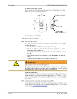
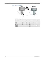
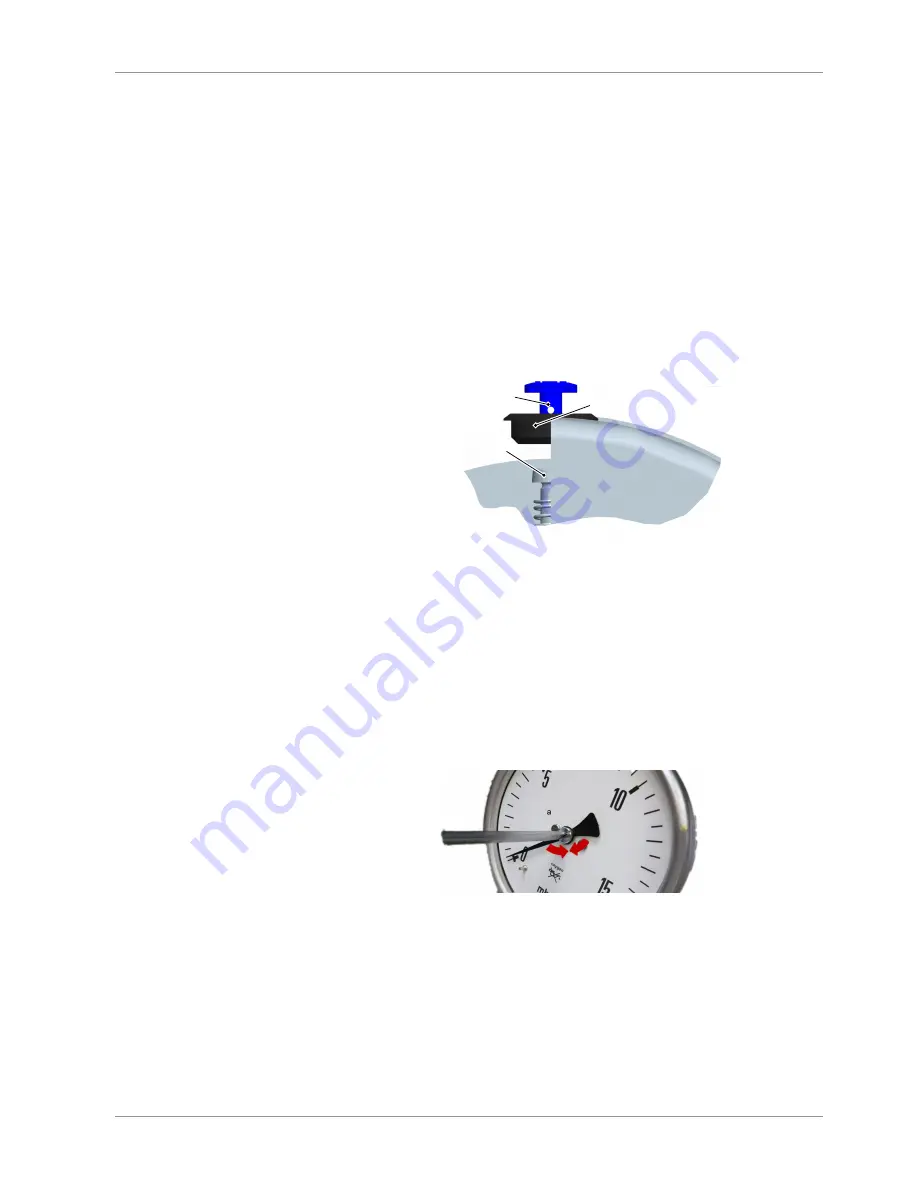
Unit with micro adjustment indicator
Micro adjustment indicators can only be used in units without a fluid filling.
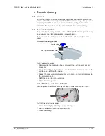
Fig. 10:
Micro adjustment indicator
1. Open the casing by releasing the bayonet ring.
2. Set the indicator to zero with a screwdriver.
3. Close the casing.


