

Alarm and Starter System
www.firstechdata.com
CM900 Master Guide
Copyright 2018 Fi rst ech ,
LLC.
Page 21
Connector 8 (CN8), 4-Pin to 4-Pin or 6-Pin (Pre-wired Antenna Cable)
Connect your antenna cable to this port. You can only use 4 to 4 pins or 4 to 6 pin antenna cables. 6 to 6
Pin antenna cables do not work. Do not use both Connector 9 and Connector 10 at the same time. Pin 1
Yellow - RX input. This wire receives the signal from remote.
Pin 2 White - TX output. This wire transmits the signal to remote.
Pin 3 Red - Constant 12V positive (+) output.
Pin 4 Black - Ground
Connector 9 CM900AS ONLY (CN9), 2-Pin (Pre-wired LED) **WHITE connector Note: Do not mistake
for Thermistor port. Note: The LED will stay solid blue when armed for the duration of the sensor set up
time. (Approx. 25 seconds)
Pin 1 Black - L.E.D negative (-) ground.
Pin 2 Black/White- L.E.D. 2.5V positive (+) output.
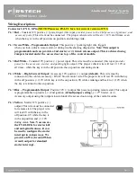
Connector 10 CM900AS ONLY (CN10), 4-Pin (Pre-wired FT Shock Sensor)
Pin 1 Black - Negative (-) ground when armed (GWA).
Pin 2 White - 2nd stage negative (-) input. (Instant trigger)
Pin 3 Red - 12V positive (+) output.
Pin 4 Yellow - 1st stage negative (-) input. (Warn away)


