background image

AerPOS Series AP-3435


19 


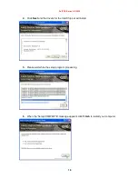
4.  Click Next and the drivers for the Intel Chip set will install. 


5.  Please wait while the setup program processing. 


6.  When the 'Setup COMPLETE' message appears click Finish to restart your computer. 


Summary of Contents for AerPOS AP-3435

Page 1: ...1 A Ae er rP PO OS S U Us se er r s s M Ma an nu ua al l Version 0 5 AP 3435 15 Bezel Fanless POS system...

Page 2: ...y for its use nor for any infringements upon the rights of third parties which may result from its use The material in this document is for product information only and is subject to change without no...

Page 3: ...n it Do not place anything over the power cord 10 All cautions and warnings on the equipment should be noted 11 If the equipment is not used for a long time disconnect it from the power source to avoi...

Page 4: ...r 3 3 1 15 5 Software Installation and Setup 15 Please follow this installation sequence 15 SMbus Driver Installation 16 SMbus Driver Installation for Windows XP 16 Chipset Driver Installation 18 Inte...

Page 5: ...shooting 43 Touch Panel Does Not Work 43 OSD Panel Cannot Work Precisely 43 Cannot Detect SATA Storage HDD SSD 43 PS 2 Keyboard Is Not Functioning Normally 44 LAN Is Not Functioning Properly 44 COM1 C...

Page 6: ...ent choice for noise free environment applications with optimized product reliability Main Features The high quality of resistive touch or durable tempered glass of projective capacitive touch both ar...

Page 7: ...h Display Power Switch HDD LED USB Port Display OSD 2 5 SATA Drive Access VFD LCM MSR Finger Print Receiver RFID i Button Cable Access 11 6 15 2nd Display Power Switch Status Blue LED Power ON Red LED...

Page 8: ...AerPOS Series AP 3435 3 AP 3435 Dimension D 235mm W 240mm H 360mm W 370mm...

Page 9: ...ard LPT Parallel port connector for printers or KeyPro solution PS 2 PS 2 connector Connect the keyboard or mouse to this port Cash Drawer RJ 11 Connect to 12V Cash Drawer Line Out Earphone connector...

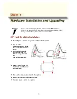
Page 10: ...e of the terminal body 3 Flip the maintenance door and Extract 2 5 SATA storage bracket out no cable connected 4 Place storage driver on the bracket and fasten it with 4 screws 5 Restore the maintenan...

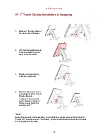
Page 11: ...isplay Module 2 Insert the MSR RFID Finger Print Receiver I button Module into USB A Type Connector Fix the Touch Display Module with one screw 3 Make sure the USB connected and screw is fastened well...

Page 12: ...ting 5 Remove back cover of the terminal by two screws on the top side 6 Select COM port Power by jumper 3 Please aware Pin1 location and make sure the correct power voltage is selected for serial dev...

Page 13: ...over Installation Notice According to the Thermal Reliability please ensure the Hooks of Back Cover are well assembled into the terminal main chassis during the remove and re installation back cover W...

Page 14: ...12V power Please note When VFD LCM is integrated please remove the external COM3 from the Rear IO to prevent the serial devices are conflict with each other by using the same COM 3 4 Make sure 12V is...

Page 15: ...t and Adjust the VFD LCM angle into proper position Memory DDRIII RAM Installation 1 Unfasten and remove the back cover 2 Install DDRIII memory 3 Before restore the top cover please check the thermal...

Page 16: ...2nd Display Installation 1 Remove the VFD plastic cover 2 Assemble the 2nd screen with bracket with 4 screws 3 Assemble the 2nd Screen with bracket to Terminal 4 Fasten 3 screws 1 on top 2 underneath...

Page 17: ...rminal 3 Display and main body units are separated 4 Reverse the process can assembly back the Touch Display Module please make sure the touch display module is firmly connected to the docking slot No...

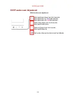
Page 18: ...ight Power finger touch for 2 seconds Back Light Power On Blue LED indication Back Light Power Off Red LED indication Button Down finger touch for 2 seconds Back Light Dimmer Down Button Up finger tou...

Page 19: ...e refer to trouble shooting Up to two cash drawers may be driven from this port Driving voltage of the solenoid is DC 12V I O port 284 is used for drawer operation A test program is supplied for Linux...

Page 20: ...d d S Se et tu up p AP 3435 comes with a variety of drivers for different operating systems You can download all the necessary drivers and utilities from http www fecpos com Please follow this install...

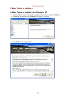
Page 21: ...nstallation SMbus Driver Installation for Windows XP 1 Download drivers from FEC website or insert the Driver CD into your CD ROM Drive 2 Double click Setup exe and Click Next to start driver installa...

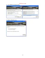
Page 22: ...AerPOS Series AP 3435 17 4 choose Next for the following steps 5 Finish and Restart system...

Page 23: ...t Driver Installation Intel ATOM D525 Chipset Installation Utilities for Windows XP 1 Download drivers from website or insert the CD into your CD ROM Drive 2 Open Setup exe and Click Next 3 Read the L...

Page 24: ...ries AP 3435 19 4 Click Next and the drivers for the Intel Chip set will install 5 Please wait while the setup program processing 6 When the Setup COMPLETE message appears click Finish to restart your...

Page 25: ...35 20 VGA Driver Installation GMA3150 driver installation for Windows XP 1 Download drivers from website or insert the CD into your CD ROM Drive 2 Execute Steup exe 3 Select Next and click Yes of Lice...

Page 26: ...AerPOS Series AP 3435 21 4 Select Next to continue driver installation 5 Finally Finish and Restart the system...

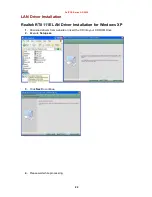
Page 27: ...AN Driver Installation Realtek RT8111E LAN Driver Installation for Windows XP 1 Download drivers from website or insert the CD into your CD ROM Drive 2 Execute Setup exe 3 Click Next to continue 4 Ple...

Page 28: ...AerPOS Series AP 3435 23 5 Click Finish to complete the installation procedure...

Page 29: ...er Installation Realtek ALC269 Audio Driver Installation for Windows XP 1 Download drivers from website or insert the CD into your CD ROM Drive 2 Double click WDM_R253 exe 3 Click Next to continue 4 C...

Page 30: ...tility Raydium controller FEC Projective Capacitive Touch Utility Introduces 1 Activate Calibration 2 Mode of FEC Capacitive Touch Panel and default settings 3 Capacitive Touch User Configuration 4 F...

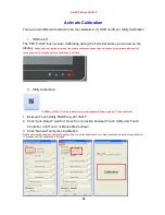
Page 31: ...he touch panel for 10 seconds until the calibration is finished 2 Utility Calibration RADPara_20130417 Utility is able to run within windows XP and windows 7 OS environment 1 Execute Touch Utility RAD...

Page 32: ...ouch Mode Dual Touch with two fingers via Touch Utility but it has to be in Win7 or POS Ready 7 OS environment Mode setting can be done in the utility 1 Execute the touch utility 2 Choose Auto Detect...

Page 33: ...P 3435 28 3 Default setting includes Default mode Mouse Mode Default Sensitivity 20 Assist Double Click Pixel 30 pixel square Right Click delay 2 seconds Click Response Time 5 Initial Contact 30 FW Ve...

Page 34: ...the overall touch experience is good Default factory setting 20 is the most optimized to fit with majority of POS environments 2 Assist Double Click sensing tolerance distance between double click Th...

Page 35: ...initial time after re upload the F W from utility this value is from 1 250 seconds Note the most optimized Initial Time is 30 seconds 6 Tick to enable the right click function 7 After choose the righ...

Page 36: ...etect wait for 10 sec for connection between Touch Utility and Touch Controller until Mouse Touch Mode shown You can read the current F W version XXXXXXA1 from the bottom of the utility 3 Choose right...

Page 37: ...Series AP 3435 32 5 wait for 10 20 second for updating F W click OK when pops out updates firmware finish window 6 Re confirm the F W is updated click auto detect to re check the proper firmware is u...

Page 38: ...unction for 2nd Screen The current Raydium touch firmware 130327A1 can only support 2nd touch screen in touch mode of Win7 or POSReady 7 OS The function of Second Display from this utility is not avai...

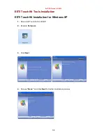
Page 39: ...AP 3435 34 EETI TouchKit Tools Installation EETI TouchKit Installation for Windows XP 1 Down load Touch Kit for WinXP 2 Execute Setup exe 3 Click Next 4 Choose None and Click Next for further install...

Page 40: ...AerPOS Series AP 3435 35 5 Click OK to close the pop up dialog 6 Click Support Multi Monitor System and then Next to continue 7 Click Next and choose a program folder to Touch Kit then Next...

Page 41: ...s AP 3435 36 8 Touch Controller found in USB then Click Yes 9 Click OK and turn off the computer to restart your system again After the system finish rebooting follow the instruction to calibrate the...

Page 42: ...es AP 3435 37 EETI TouchKit Installation for Windows 7 1 Down load Touch Kit for Win 7 setup exe 2 Execute Setup exe 3 Click Next 4 Un tick Install RS232 interface driver and Click Next to go for furt...

Page 43: ...AerPOS Series AP 3435 38 5 Click Yes and confirm the USB touch controller is plugged 6 Click Support Multi Monitor System and then Next to continue...

Page 44: ...and turn off the computer to restart your system again After the system finish rebooting follow the directions to calibrate the Touch screen TouchKit Control Panel This section explains the different...

Page 45: ...POS Series AP 3435 40 The general tab allows you to Manage the touch screen controller you installed Tools tab The tools tab allows you to Calibrate the touch screen with the 4 Points Calibration butt...

Page 46: ...AerPOS Series AP 3435 41 Wireless LAN Driver Installation Wireless LAN Driver Installation for all Windows Operating Systems Optional 1 Download drivers from website 2 Run Setup EXE 3 Click Next...

Page 47: ...Tempered Glass 5W Resistive Backlight LED CCFL Brightness 350 nits 250 nits Touch Display Backlight MTBF 50 K hours 30 K hours MSR Track 1 2 3 USB interface Finger Print Reciever Optical Finger Print...

Page 48: ...Check if the FEC AUO Capacitive touch is automatically detected by Windows 7 or properly installed the touch driver in Windows XP E Check well cabling between touch panel and touch controller F Capac...

Page 49: ...driver is installed properly B Check if there are any IRQ conflicts C Check if the RJ45 cable is properly connected D The on board LAN chip could be defective COM1 COM5 Are Not Functioning Properly A...

Reviews: