22
£
5.
Smoke or unburned combustion gases absorb ultra-violet energy. On installations with negative
pressure combustion chambers, a small hole drilled in the UV1A, UV2 sight pipe will assist in
keeping the pipe clean and free from smoke. For positive pressure furnaces, provide clean air to
pressurize the sight pipe, if necessary.
6.
Two UV1A or UV2 Scanners may be installed on the burner if it is necessary to view two areas
to obtain reliable detection of the flame. They should be wired in parallel. Only one repetitive
selfchecking 45UV5 Scanner may be installed on a burner.
7.
To increase scanner sensitivity with UV1A, UV2 Scanners, a quartz lens permits location of the
scanner at twice the normal distance. Use l/2" x 1 l/2" pipe nipple between UV1A Scanner and
the coupling. Use 3/8" pipe nipple and a l/2" x 3/8" bushing on UV2 installations.
8.
Request the assistance of any Fireye field office for recommendations of a proper scanner instal-
lation on a non-standard application.
TYPICAL SCANNER INSTALLATIONS
OPERATION — 45UV5 & 55UV5 SELF-CHECKING UV SCANNER
Self-checking ultra-violet scanners should be used in applications where burner firing operation is
continuous or where the burner is on for long periods of time without recycling. In addition, ultra-
violet self-checking systems are mandatory in some locations.
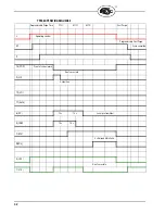
The operation of this type of system consists of maintaining the flame scanning capability at all times
while also proving that the ultra-violet tube is firing properly. This is done periodically by mechani-
cally closing off the sight of the UV tube and checking to make sure that the flame signal goes away.
A shutter assembly in the 45UV5 scanner performs this function. The diagram below explains the
process further.
If the shutter assembly in the scanner fails, the tube is faulty, or there is insufficient power to the
scanner, the BurnerLogix will LOCKOUT and display the following message LOCKOUT CHECK
SCANNER. The ultra-violet tube is replaceable (P/N 4-314-1).
A lockout will result if a minimum signal is detected for three consecutive shutter closed periods.
The maximum UV signal
from a flame is found in the
first one-third of the visible
flame taken from the point
where the flame begins. The
scanner sight pipe should be
aimed at this area.
DO NOT EXTEND
MORE THAN
HALF-WAY INTO
REFRACTORY
SCANNER
FORCED
CLEAN AIR
(FROM DISCHARGE
OF FAN)
METHODS OF COOLING SCANNER
INSULATING
TUBING
SEALING UNION
FORCED
AIR
EXTEND SIGHTING TUBE
6”(152.4) OR 8”(203.2)
DO NOT EXTEND MORE THAN
HALF-WAY INTO REFRACTORY


