


COMMONLY ASKED QUESTIONS
(
cont.
)
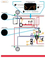
In the WR8-760-2230 system, which port from valve block goes to & from the dryer?
Each port on the valve block is labeled for the designated connector. Using the air line tubing, measure the distance from each port of the dryer
back to the valve block. The air line tubing should be routed from the I.D. (inflow to dryer) port on the valve block to the in port on the dryer. The
next air line tubing should be routed from O.D. (outflow from dryer) port on the valve block to output side of the dryer. Cut the air line tubing
accordingly, as squarely as possible. Push the air line tubing into the fittings as far as possible.
What do all of the abbreviations on the valve block refer to in the WR8-760-2230 IntelliRide System?
O.D. = outflow from dryer R.F. = right/front air spring L.F. = left/front air spring I.D. = inflow to dryer P.S. = pressure sensor L.R. = left/rear air
spring R.R. = right/rear air spring EX. = exhaust COMP. INLET = compressor inlet
What do I do with the park wire if I have a manual transmission in the WR8-760-2230 IntelliRide system?
The park wire needs to be connected to a ground or to a customer supplied switch that will be grounded when the vehicle is NOT in park. One
potential input is the parking brake.
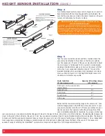
In step 3 of Height Sensor Installation of the WR8-760-2230 Installation Instructions it mentions that the sensor arm and linkage
should not be inline. What does that mean?
The best description is shown in the upper right-hand corner on page 6 of the 2230 Installation Instructions, Figure 3. Too big of an angle between
the height sensor arm and link will pull the sensor and may allow the arm to toggle over center.
Why should I use the thermal sleeves provided within the WR8-760-2230 IntelliRide system?
Thermal sleeves have been provided for to protect tubing from direct heat from the engine and exhaust pipe. If a thermal sleeve is required simply
slide the sleeve over the air line tubing to the location requiring protection.
How does the system indicate that the programming portion of the installation is complete in the WR8-760-2230
IntelliRide system?
In step 5 of programming the vehicles heights there is an indication that the process is completed. Please proceed with the instructions as speci-
fied in the included 2230 Installation Instructions. When the vehicle is at the calibration height, hold the program switch for eight seconds, and
then release. Both lights on the height selection switch should be on at the completion of programming. FYI: The lights will not turn on immediate-
ly at the completion of programming. Please allow a maximum of 30 seconds.
Are the height sensors environmentally protected?
The height sensors are IP68 rated, meaning they can withstand a water depth of 1/2-meter. These height sensors have survived severe off road
driving conditions in water, snow and mud.
Where should the ignition wire on the WR8-760-2230 aftermarket IntelliRide system be connected?
The purple ignition wire should be connected to a source with less than 1/2 amps. Typically a standard ignition wire under the dash of the vehicle
is suitable. A source with more than 1/2 amps can potentially damage the ECU.
What type of dryer is used with our system?
The dryer is regenerative. This means that the dryer is maintenance free assuming that there is not a leak in the system. A leak would not allow the
system to exhaust enough air through the dryer to adequately dry the air.
How much current does the IntelliRide electronic air spring system pull?
When the system is off the ECU draws less than a battery powered watch. When the system is on the max draw is dependant on how many valves
are in operation, i.e. when no valve activity then we draw less than 1 amp but for each valve up to 1.5/2.0 amps, three valves being the most open
at one time. The height indicator lights are LED’s and draw very little current.
Why does the compressor relay need to be mounted inside the engine compartment?
The relays are not sealed units. This is why it is recommended that they are installed inside the engine compartment.
11
Summary of Contents for 4-corner
Page 1: ......
Page 19: ...TECHNICAL 15...


