Firestone 4-corner Installation Instructions Manual Download Page 10

6

HEIGHT SENSOR INSTALLATION 

(cont.)

Step 4

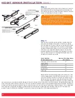
To install the height control sensor, refer to Figure 4a, 4b and 5, to
become familiar with the mounting geometry and hardware. Be
sure that the area above and below the sensor location on the axle
is clear of obstructions for the arm to move.

Step 5

Take the sensor under the vehicle and find a location where the
sensor may be attached to the vehicle so that the arm extends
over the suspension. The arm of the sensor must be able to travel
from full jounce to full rebound for the system to work properly.
Looking at the table below pick out a hole on the sensor arm that
will work on your suspension attachment point. The use of the
provided template will show minimum and maximum arm move-
ment as shown in Figure 3. At ride height the height sensor arm
should be as horizontal as possible.

Hole location

Approx. Working range

(from sensor out)

(of sensor)

First hole on the sensor arm 

2”

itself (6mm)

Second hole 

3”

Third hole

4”

Fourth hole 

5”

Fifth hole

6”

Notice that the maximum working range of the sensor is 6”, even
with the linkage placed in the fifth hole of the sensor arm. If your
suspension provides more than 6” of travel, you will have to posi-
tion the sensor so that operates within the yellow portion of the
sensor installation template. For example, if you have a 4-link type

rear suspension, you can simply locate the linkage a bit closer to the pivot of the 4-link arm on one of the 4-link bars. By attaching the linkage a bit
closer to the pivot of the 4-link arm, the sensor “sees” less suspension movement than if it were attached directly at the axle location. The object is
to make sure that the suspension movement does not move the sensor arm out of its range of authority as outlined in Figure 3. On an independent
front suspension, simply place the linkage somewhere inboard of the ball joint to effectively lessen the travel of the sensor. If the sensor arm
exceeds it range of authority, the IntelliRide™ system will not respond. See page 12 & 13 for diagnostic information.

What direction do the height sensors need to be mounted with the

WR8-760-2230 IntelliRide system?

If provided with a wire harness the power and ground to each vehicle corner
expects the height sensor arm to be in a certain position relative to the body of
the sensor. If mounted backwards the system would act in reverse, or not at
all. The height sensors on the right side of the vehicle need to be mounted with

the arm in the 9:00 position. The height sensors on the left side of the vehicle

need to be mounted with the arm in the 3:00 position.

Summary of Contents for 4-corner

Page 1: ......

Page 2: ...Installation or service charges for replacement parts 2 Damage caused by incorrect installation 3 Parts that have been altered or tampered with 4 Damage caused by vehicle accident 5 Damage from misuse...

Page 3: ...at Washer 8 M5 x 8 mm Machine Screw 8 M6 x 16 mm Machine Screw 4 M6 Nylon Lock Nut 4 Height Control Arm 4 Hardware Required for Height Sensor Linkage Installation Refer to Figure 6 Hose Clamp 4 Axle M...

Page 4: ...he Park Wire Connector to ECU to be mounted inside the vehicle Service Switch to be used to turn the system on and off Ignition wire and ground wire Ignition wire should be connected to a source less...

Page 5: ...HEIGHT SENSORS 6 1 4 TUBING 18ft 7 WIRE HARNESS FULL SYSTEM 8 AIR DRYER SYSTEMS 9 BRACKET HEIGHT SENSOR 10 3 8 NPT FITTING 1 4 TUBE 11 1 8 NPT FITTING 1 4 TUBE 12 1 4 NPT FITTING 1 4 TUBE 13 1 4 NPT...

Page 6: ...e mounted under the dashboard and the harness ran through the firewall to corresponding corners valve block and power connections Valve Block The valve block should be placed in a protected location t...

Page 7: ...d 3 16 flat washers located in your hardware pack Proper mounting of this compressor will provide maximum isolation DO NOT OVER TIGHTEN further tightening will crush the insert and isolator and reduce...

Page 8: ...the wire harness Simply pull the switch off the connector to mount it to your vehi cle After mounting the switch to the vehicle reconnect the switch to the wire harness The switch should click into t...

Page 9: ...ion is fully extended to damper limit Then to determine the jounce suspension position that you will need to mount the height sensors just jack the sus pension up to that point into the jounce stop Ma...

Page 10: ...si tion the sensor so that operates within the yellow portion of the sensor installation template For example if you have a 4 link type rear suspension you can simply locate the linkage a bit closer t...

Page 11: ...ow set Slowly move suspension to the opposite end of its travel ensuring that the sensor arm stays within the limits of the template The parts that you will need for the linkage are M5 threaded rod tw...

Page 12: ...eight seconds The top light on the height selection switch should start blinking This will indicate that the highest height needs to be programmed into the ECU STEP 4 Programming Highest Height Set th...

Page 13: ...d Height is designed to be used for show or ease of ingress and egress from the vehicle The vehicle should not be driven in this mode Ride Height is designed to be the primary operating position of th...

Page 14: ...to withstand the most severe vehicular environments The sensor has been used on high mileage and off road applications The tensile load that the arm has withstood approximately 600lbs in an applicatio...

Page 15: ...to the location requiring protection How does the system indicate that the programming portion of the installation is complete in the WR8 760 2230 IntelliRide system In step 5 of programming the vehi...

Page 16: ...sensors to the corresponding corners as indicated on the wire harness On the WR8 760 2230 IntelliRide system the height change up will not work will not level up The current height is displayed on th...

Page 17: ...s locked down no function The system will not level or change height The lights toggle slowly The ground is removed from the valve block Check grounding on valve block wire The WR8 760 2230 system is...

Page 18: ...For the latest technical information and support questions answers please visit www fsip com ir 14...

Page 19: ...TECHNICAL 15...

Page 20: ...Firestone Industrial Products Company 12650 Hamilton Crossing Blvd Carmel IN 46032 5400 www fsip com Intelliride...

Reviews: