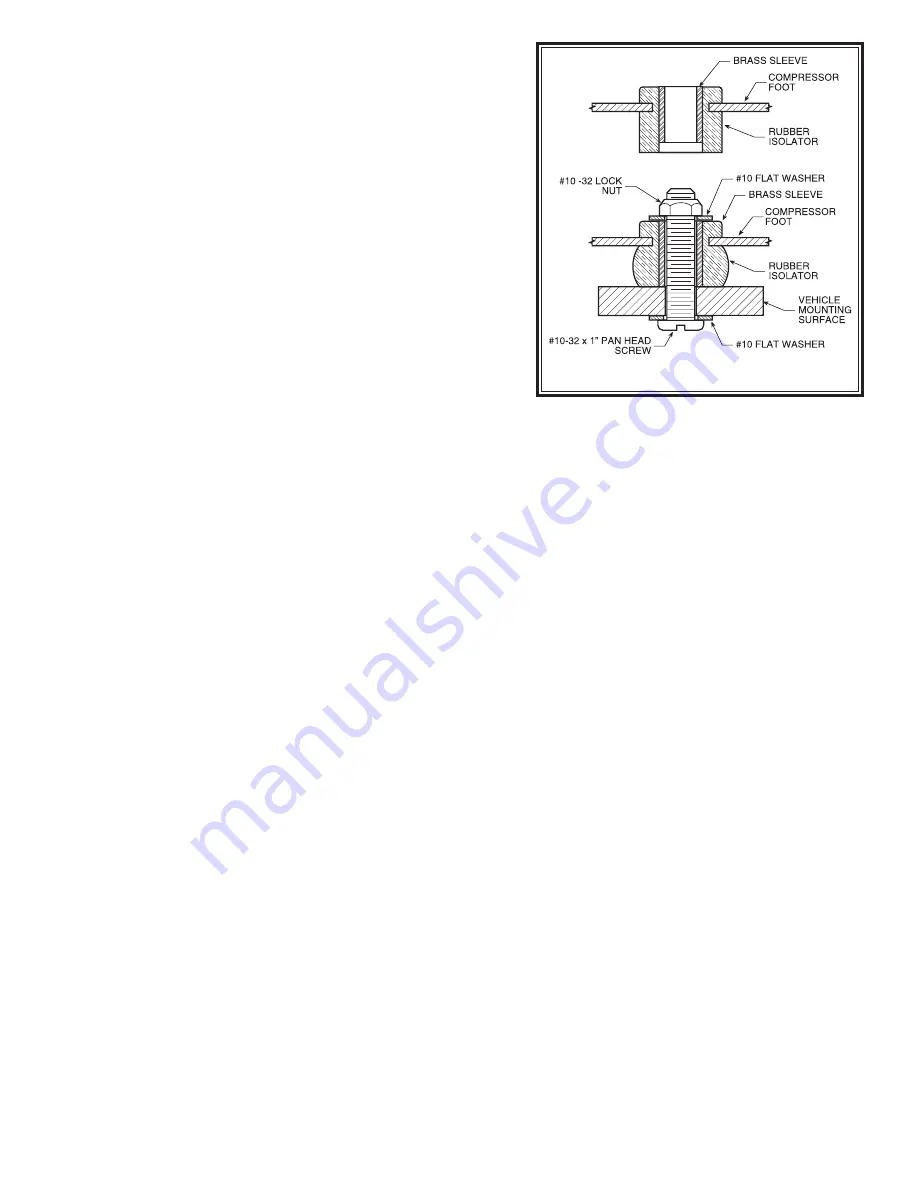
Figure “B”
STEP 1—MOUNT THE COMPRESSOR
Begin by removing the negative battery cable. Select a conve-
nient location to mount the compressor. This location should
provide ample air flow and be protected from airborne debris
and moisture. The mounting surface should be rigid to sup-
port the compressor. The compressor is oil-less and can be
mounted in any orientation necessary for installation. Make
sure that the wire harness will reach form the compressor to
the anticipated location of the gauge panel. Install a male fitting
into the treaded output port on the compressor head,
see Fig-
ure “A”
. Tighten the fitting sufficiently to engage at least two
threads with the pre-applied thread sealant.
DO NOT OVER
TIGHTEN THE FITTING.
Mark the four compressor mounting
holes using the compressor as a template and a center punch,
then drill four 3/16” holes. Mount the compressor using the
supplied 10-32 x 1” machine screw, 10-32 nylock nuts and
3/16” washers.
See Figure “B”.
Attach the black wire from
the compressor to a convenient ground source on the vehicle.
STEP 2—MOUNT THE MANIFOLD BLOCK
Select the valve block from your kit and install the pressure
sensors into the top of the valve block in the holes marked
PS1
and
PS2
.
See Figure “A”.
Select a convenient location
to mount the valve block near the compressor. Mark the two mounting holes using the valve block as a template
and a center punch, then drill two 9/32” holes. Mount the valve block using the supplied 1/4”-20 x 2-1/2” bolts
and 1/4” nylock nuts.
STEP 3—WIRE HARNESS FORM THE COMPRESSOR AND VALVE BLOCK
Insert the red/blue wire from the wire harness with the male spade terminal into the female spade terminal on the
red wire from the compressor. The other red wire in the wire harness with the fuse will be connected to a 12 Volt,
20 Amp positive power source.
See Figure “A”
. Attach the brown and green wires with ring terminals from the
wiring harness to the studs on the pressure sensor in RF/RR, and the violet and grey wires with ring terminals from
the wiring harness to the studs on the pressure sensor in LF/LR. Tighten the nuts on the pressure sensor terminals
figure tight.
DO NOT OVERTIGHTEN THE TERMINAL NUTS.
See Figure “A”.
STEP 4—MOUNT THE GAUGE PANEL
The gauge panel must be mounted in a dry protected location with a flat mounting surface. Install the four Velcro
tabs ontp the back of the gauge panel and then firmly place the gauge panel onto the mounting location.
STEP 5—WIRE HARNESS FOR THE GAUGE PANEL
Connect the black wire from the gauge panel wire harness to a suitable ground and the red wire to 12V ignition
activated source. Route the wire harness from the compressor and manifold block to the gauge. Use the Nylon ties
provided to secure the wire harness to the vehicle. Route the wire harness to avoid direct heat from the exhaust
system and away from any sharp edges. Insert the male connector into the female connector until a clicking noise
is heard.
See Figure “A”.
STEP 6—ROUTE THE AIR LINE
Cut a section of air line tubing that will reach from the compressor to the valve block. Cut the air line tubing as
squarely as possible and insert the tubing into the male fitting on the compressor and then into the fitting on the
valve block marked
IN
. Cut a section of air line tubing that will reach from the valve block to one of the air springs.
Cut the air line tubing as squarely as possible and insert the tubing into the fitting on the valve block and then insert
the other end into the air spring. Use the Nylon ties provided to secure the air line tubing to the vehicle. Route the
tubing to avoid direct heat from the exhaust system and away from any sharp edges. Repeat this last step on the
other air spring and remaining fitting.
STEP 8—CHECK THE SYSTEM
With the Light Duty Electronic Air Command™ kit and the air springs installed you are ready to test the system.
Re-attach the negative battery cable. Turn on the vehicle’s ignition. Push and hold the up button to inflate the air
springs. The gauge will display how much air pressure is in the system. Inflate the air springs to 70 psi or the max
air spring pressure, which ever is less, and check the fittings for air leaks with a solution of soap and water. If a leak
is detected at a tubing connection, check to make sure that the tube is cut as squarely as possible and that it is
pushed completely into the fitting. The tubing can easily be removed from the fitting by first releasing the pressure
from the air spring, then by pushing the collar towards the body of the fitting and holding, then pulling the tube out.


