Page | 9
3.
Siren/Strobe Circuit:
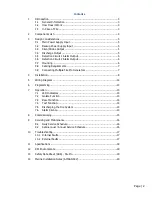
Mount the siren/strobe (P/N FP-08940) in a location where it is
visible and audible in all points with the risk area and connect
to the “Siren” output on the
module (marked orange). If more than one siren/strobe is being installed, they are to be
connected using the secondary positive/negative terminals in the sounder.
The supplied end-of-line diode should be installed in the secondary positive/negative
terminals of the last siren/strobe in the circuit. The diode is polarised, so the positive lead
of the diode (marked with a grey band) should be terminated in the positive terminal of
the siren/strobe, otherwise a fault will occur on the fire control panel.
4.
Circuit 1 Alarm Circuit:
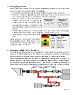
This circuit can be programmed for
ALARM ONLY
(operate
siren/strobe) or
AUTOMATIC DISCHARGE
(discharges suppression system and operates
siren/strobe). If detection is not used, the supplied end-of-line plugs (marked green) must
be connected to the Circuit 1 Alarm output.
-
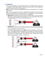
Manual Call Point:
Manual Call Points (P/N FP-14053) can be connected together in
quantities up to 30. If a manual call point is being used for remote activation, it
must
be installed on Circuit 1 Alarm. The supplied end-of-line plugs (marked green) must be
connected to the last manual call point in the circuit.
-
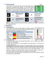
Linear Heat Detection:
Linear Heat Detection can be installed in lengths up to 100m.
Any terminations of cable must be enclosed using sealed, metal enclosures from the
LHD Install Kit (P/N FP-09511). P-Clips must be installed at intervals of 50cm maximum
to support the cable. The supplied End-of-line junction box must be installed on the
end of the cable.


