Firepower FP-90 Instruction Manual Download Page 25

21

P

ROBLEM

1. Dirty, porous or brittle weld.

2. Arc Works but is not feeding wire.

3. When trigger pulled, there is no wire

feed, weld output or gas flow.
Fan does not operate.

4. Wire feeding but there is no arc.

5. Fan operates normally, but when gun

trigger pulled, there is no wire feed,
weld output or gas flow.

6. Non-penetrating weld or low output.

7. Wire is birdnesting at the drive roller.

8. Wire burns back to contact tip.

9. Workpiece clamp and/or cable gets

hot.

10. Gun nozzle arcs to work surface.

11. Wire pushes torch back from the

workpiece.

12. Wire sticks onto the contact tip.

P

OSSIBLE

 C

AUSE

Plugged welding nozzle.

Faulty wire speed control assembly.
No tension on the drive roller.
Faulty drive motor (very rare).

Incorrect voltage.
No power.
Circuit breaker in off position.

Bad ground or loose connection.

Bad connection to gun or faulty gun.

Faulty trigger on gun.
Faulty transformer (rare).
Exceeded duty cycle: thermal protector
has opened.

Loose connection inside machine.

Too long or improper extension cord.
Wrong size wire.
Poor ground connection.

Wrong size contact tip.
Loose Gun connection or faulty gun
assembly.

Too much tension on drive roller.
Gun liner is dirty, worn or damaged.
Contact tip is clogged or damaged.
Liner is stretched or is too long.

Gun liner is worn or damaged.
Wrong size contact tip.
Contact tip clogged or damaged.
Liner is stretched or is too long.
Wire is not feeding correctly.

Bad connection from cable to clamp.

Slag buildup inside nozzle or nozzle is
shorted.

Excessive wire speed.

Low wire feeding.

R

EMEDY

Clean or replace welding nozzle.

Replace wire speed control assembly.
Adjust the drive tension.
Replace drive motor.

Check for correct voltage.
Confirm power switch is on.
Reset circuit breaker.

Check ground and connections. Tighten
as necessary.
Check connection to gun or replace gun.

Replace trigger.
Replace transformer.
Allow welder to cool at least 10 minutes.
Maintain appropriate duty cycle.

Blow inside machine out with com-
pressed air. Clean and tighten all connec-
tions.
See extension cord use in this manual.
Use correct size welding wire.
Reposition clamp. Check cable to clamp
connection.
Use correct size contact tip.
Tighten gun or replace gun.

Adjust the drive tension.
Replace gun liner.
Replace contact tip.
Trim liner to proper length.

Replace gun liner.
Use correct size contact tip.
Replace contact tip.
Trim liner to proper length.
Adjust drive tension.
Adjust wire spool brake.

Tighten connection or replace cable.

Clean or replace nozzle as needed.

Decrease wire speed.

Increase wire speed.

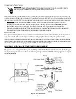
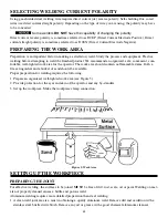
TROUBLESHOOTING INFORMATION

Use this chart to assist you in resolving common problems you may encounter. These are not all of the possible
solutions.

Summary of Contents for FP-90

Page 1: ...FP 90 Gasless Welding System FCAW Instruction Manual FORM NO 0056 1839 EFFECTIVE July 2001 Safety and Operating Instructions For Your Safety PLEASE READ CAREFULLY...

Page 2: ......

Page 3: ...6 Power Requirements 6 Connection to Power Source 6 Extension Cords 6 Installation of the Welding Wire 7 Welding Torch 8 Gasless Welding 8 Advantages of Gasless Welding 8 Preparation for Welding 9 Wel...

Page 4: ...Figure 3 Polarity Preparation 9 Figure 4 Power Source 10 Figure 5 Work Area 12 Figure 6 Workpiece Preparation 13 Figure 7 Types of Weld Joints 13 Figure 8 Gun Position Angle A 15 Figure 9 Gun Position...

Page 5: ...nd operation Items in this manual that significantly affect safety are identified with the following headings Please read and understand this manual Pay special attention to items identified with thes...

Page 6: ...D PROPERTY DAMAGE Reduce the risk of death injury or property damage from fire or explosion Read understand and follow the following safety instructions Additionally make certain that anyone else who...

Page 7: ...rcury chromium graphite lead cadmium or beryllium unless the operator and the people standing in the same area use an air supplied respirator SAFETY INSTRUCTIONS For your safety BEFORE connecting the...

Page 8: ...ons 1 If there is interference in the power source line mount an E M T filter between the power supply and the power source 2 Shorten the output cables of the power source keep them together and conne...

Page 9: ...er the internal thermal overload protection shuts off all welder functions If this happens DO NOT SHUT OFF THE WELDER Leave the welder turned on and the fan running After the welder is properly cooled...

Page 10: ...DO NOT obstruct the air intake and output vents A reduced air flow can cause a reduced duty cycle and damage internal compo nents 5 Insure at least 6 feet of open space on the each side of the welder...

Page 11: ...ified electrician if this problem exists Improper performance and or damage to the welder will result if operated on inadequate or excessive power Extension Cords For optimum welder performance an ext...

Page 12: ...will not feed the wire 6 Connect the power supply cable to the 120 V 60 Hz line Turn on the switch Press the torch switch The wire fed by the wire feeding motor at variable speed must slide through th...

Page 13: ...ll is cor rectly positioned groove matching the wire diameter Note that each roll has two grooves One is marked 035 0 9 mm and the other is marked 030 0 8 mm WELDING PROCEDURES 1 Your welding power so...

Page 14: ...p This could cause electrical shorting between the nozzle and the workpiece Regularly inspect the conductor tube handle cable hose and other parts of the welding torch for abrasions cuts or undue wear...

Page 15: ...well oxidized spool leaves a darker line Heavy copper oxi dation causes arc flutter and possibly wire drive slippage If steel wire continues to oxidize the steel wire under the copper coating will ru...

Page 16: ...safe convenient com fortable well lighted work area for the operator The work area should contain no flammable items Both a fire extinguisher and a bucket of sand should be available Proper preparatio...

Page 17: ...anodized If the base metal pieces to be joined are thick or heavy it may be necessary to bevel the edges with a metal grinder at the point of contact as shown in Figure 6 The angle of the bevel should...

Page 18: ...CAN INJURE EYES AND BURN SKIN Reduce the risk of injury from arc rays NEVER strike a welding arc until you and all bystanders in the welding area have a welding helmet or shield in place and are weari...

Page 19: ...n most cases the optimum angle is 60 degrees the point at which the gun handle is parallel to the workpiece Increasing angle A increases penetration Decreasing angle A decreases penetration 2 Angle B...

Page 20: ...such as the puddle running downward start the vertical weld at the bottom of the weld joint Push the gun up toward the top to overcome this problem b Aluminum welding uses either direction of gun tra...

Page 21: ...ted more toward the metal above the weld joint This helps prevent the weld puddle from running downward while still allowing slow enough travel speed to achieve good penetration A good starting point...

Page 22: ...strations in Figure 18 show the sequence of laying multiple pass beads into a T fillet joint and a lap fillet joint SPECIAL WELDING METHODS SPOT WELDING Spot Welding joins pieces of metal together wit...

Page 23: ...e time right along each side of the lap joint seam Select the wire diameter heat setting and wire speed as if you were welding the same thickness material with a continuous bead SPOT WELDING INSTRUCTI...

Page 24: ...DUCATIONAL EYE AND FACE PROTECTION obtainable from the American National Standards Institute 1430 Broadway New York NY 10018 NFPA Standard SIB CUTTING AND WELDING PROCESSES obtainable from the Nationa...

Page 25: ...or is too long Gun liner is worn or damaged Wrong size contact tip Contact tip clogged or damaged Liner is stretched or is too long Wire is not feeding correctly Bad connection from cable to clamp Sla...

Page 26: ...tip 4 Sharp bends or kinks in conduit 5 Dirty or plugged conduit 6 Conduit pulled back from diffuser 7 Machine improperly adjusted 1 Loose contact tip or diffuser 2 Loose power connections 3 Loose or...

Page 27: ...23 Figure 21 FP 90...

Page 28: ...2 13 1444 0443 THERMOSTAT 1 14 1444 0433 SJT CABLE 1 15 1444 0444 LEFT SIDE PANEL 1 16 1444 0445 PLASTIC WIRE FEEDER 1 17 1444 0427 WIRE FEED ROLL 1 18 1444 0428 CABLE CLAMP FOR HOLE 1 19 1444 0446 FR...

Page 29: ...25 Figure 22 FP 90 Wiring Diagram...

Page 30: ...26...

Page 31: ...foregoing Firepower oxygen acetylene products will be covered by a two year product replacement warranty Firepower plasma cutting equipment will be covered by a one year parts labor warranty Firepower...

Page 32: ...or performance of seller s product This warranty supersedes all previous warranties U S A International Canada Europe Asia Pacific PTE Ltd Mexico Customer Service Customer Service Customer Service Eu...

Reviews: