15
NFOD42 Gas Fireplace
INSTALLATION
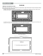
)LQLVKHG
0DWHULDO
1DLOLQJ6WULS
3RVLWLRQ
ÀXVK
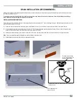
'5$,1,167$//$7,215(&200(1'('
Although this fireplace is designed to operate outdoors safely, rain and other sources of moisture may enter the hearth area, which will cause water to col-
lect inside the base of the unit.
To prevent excessive water collection, the installer must provide a way to drain the water from the base of the unit by building or installing a
water collector before positioning the fireplace in its location.
INSTALLATION INSTRUCTIONS
When planning for the installation of the unit, the framing height must be increased by 3/4", when installing a drain pan. Additional space below the unit will
also be required to plumb a drain line.
1)
Remove 4 screws to remove the rear access panel from the back of the unit - this will allow access to the drain hole at the base of the unit.
2)
On the exposed drain hole (see location below), install a PVC 3/4" threaded coupling reducer going from the top of the pan, down through the hole.
Apply a silicone-based sealant around the base and threads before installation.
3)
Holding the reducer coupling with a wrench, thread a 90
PVC elbow (from the underside of the unit) to the reducer until it is tight to the metal.
Note
: To assure proper drainage, that fireplace must be installed on a leveled surface
4)
Add additional piping to route the drain to an appropriate location.
Drain hole location at
base of the unit
Threaded
Reducer
(PVC)
Threaded
Elbow
@ 90
(PVC)
Reducer and elbow can be purchased from your local
hardware store.
Cut notches into the top
of the coupling reducer to
prevent water pooling.
Rear access panel
Drain hole
Summary of Contents for NFOD42 Series
Page 40: ...40 NFOD42 Gas Fireplace NOTES ...
Page 41: ...41 NFOD42 Gas Fireplace NOTES ...
Page 42: ...42 NFOD42 Gas Fireplace NOTES ...


