32
FCPS-24FS Series Instruction Manual —
P/N 51883:H1 4/14/2011
Applications
Split Temporal Mode of Operation
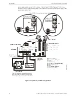
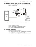
power supply output circuits 1 & 2 to turn on. Control Input #2 (TB4, Terminals 7 & 8) is con-
nected to an FACP Notification Appliance Circuit which is used to activate the power supply’s tem-
poral output circuits 3 & 4.
TB
4
JP
3
J3
TB
5
TB
2
JP1
JP
2
OUT4
-NAC4
+
OUT
4
-N
AC4+
OU
T4
-NAC
4+
OUT3
-NA
C
3
+
OUT2
-NAC
2+
OU
T
1
-NA
C
1+
AU
X
-
IN
2-
IN
2+
OUT
1-
OUT1
+
IN1-
IN1
+
SYNC
IN
-
SYN
C
IN
+
AU
X
+
NO
N
C
AUX
T
B
L
CO
M
1 2 3 4 5 6 7 8 9 10
8
7
6
5
4
3
2
1
8
7
8
7
TB2
TB2
3
2
1
+
+
+
+
+
+
+
+
+
-
-
-
-
-
-
-
-
-
T1
T11
T2
T10
T3
T9
T4
T8
T5
T7
T6
Figure 5.3 Split Temporal Mode Application
Style Z (Class A)
Style Y (Class B)
Temporal Bell Circuit 4
Temporal Bell Circuit 3
Horn/Strobe Circuit 2
Horn/Strobe Circuit 1
Use listed ELR
(4.7K
) to
terminate Style Y
(Class B) NAC
ELR not required for
Style Z (Class A) NAC
Note: All NACs are supervised and power-limited
ZNAC-4
Option Module
SW1 Switch Settings
1 & 2 = sync (any setting but
OFF/OFF)
3 = OFF (master)
4 = OFF (no AC Fail reporting delay)
5 = ON
6 = OFF
7 = OFF (charger enabled)
8 = OFF (circuit 4 NAC)
Internal Trouble Contact
Split Temporal
FACP
Control Module*
End-of-Line
Resistor supplied
with Control Module
FACP NAC
End-of-Line
Resistor
Bells
Bells
SLC
24
fsa
p
p5
tp
H2.wm
f
*If the SLC device does not match the one in this
figure, refer to the SLC manual wiring conversion
charts for legacy and newer versions of the modules.
T11
T10
T9
T8
T7
T6
T1
T2
T3
T4
T5
FCPS-24FS
NAC
(steady,
no sync)

