background image

I N S T A L L A T I O N

12.

BEFORE INSTALLING the Firecom 3010R Series Intercom, make sure you have read AND

UNDERSTOOD the ENTIRE installation procedure. You should also read the sections on

Pre-Installation (page 6) and System Orientation (page 1). If any item in the Installation

Procedure is not understood, or if you have any questions which are not addressed in this

manual, contact your local Firecom Dealer for more information BEFORE you proceed

with the installation.

MOUNTING THE INTERCOM

1.

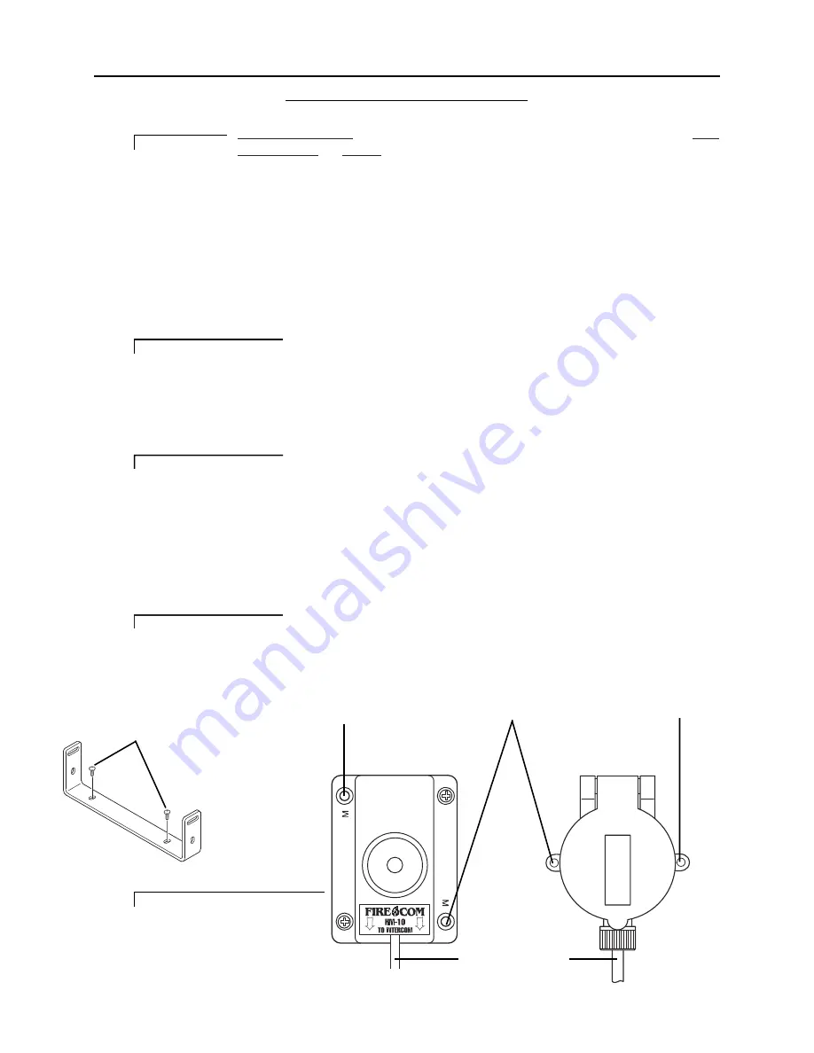
Using the mounting bracket as a template, mark the location of the mounting
holes.

2.

Using a 3/16"drill bit, drill 2 holes for the #8 sheet metal screws (supplied).

Be sure the area behind the panel you are drilling into is free of wires or other

obstructions that could be damaged while drilling the holes.

3.

Install the mounting bracket with the sheet metal screws (Figure 9).

4.

Remove the 4 screws (2 on each side) closest to the rear of the intercom unit and
mount the intercom on the mounting bracket with the 4 screws.

DO NOT completely tighten the intercom mounting hardware until the entire

installation is complete.

MOUNTING THE HEADSET MODULES

5.

Using the Headset Module as a template (Figure 10), mark the location of the
mounting holes. The holes in the HM-10 used for mounting the module are
marked with a letter “M”.

6.

Using a 5/32"drill bit, drill 2 holes for the #6 sheet metal screws (supplied).

Be sure the area behind the panel you are drilling into is free of wires or other

obstructions that could be damaged while drilling the holes.

7.

Position the Headset Module and secure with the provided sheet metal screws.

IMPORTANT

IMPORTANT

IMPORTANT

IMPORTANT

Mounting Hole

Mounting Hole

Mounting Hole

CA Cable To Intercom

FIGURE 10:

Headset Modules

FIGURE 9:

The Mounting Bracket

#8 Sheet Metal Screws

Summary of Contents for 3010R INTERCOM

Page 1: ...I N S T A L L A T I O N O P E R A T I O N M A N U A L 3020R 3010R FIRE APPARATUS INTERCOM SYSTEM 3020R INTERCOM 3020R REMOTE HEAD ...

Page 2: ......

Page 3: ...N 6 Intercom Location 6 Headset Modules 7 Daisy Chaining the Headset Modules 8 Routing the CA Cables 9 Intercom Connections 10 Intercom Adjustments 11 Optional Foot Switch 11 INSTALLATION 12 Mounting the Intercom 12 Mounting the Headset Modules 12 Installing the CA Cables 13 Power Ground Connections 14 Radio Connections 15 Intercom Adjustments 16 Auxiliary Input Output 17 Installing The Remote Hea...

Page 4: ...the apparatus radio from any headset position in the system Intercom Only headsets will not transmit over the radio The 3010R Series Intercoms feature advanced circuitry that effectively suppresses distracting background noise and eliminates clipping without affecting communication The result is clear crisp on board communication like never before There are 2 models of intercoms in the Firecom 301...

Page 5: ...E ASSEMBLY Provides the power connections for the 3010R Series Intercom Unit The power connections should be made at the same place as the power connections for your radio HM 10 HEADSET MODULES Headsets are plugged into the Headset Modules to interface them into the system The HM 10 is the standard Headset Module for use inside the apparatus PP 20 PUMP PANEL MODULE A water resistant Headset Module...

Page 6: ...CATOR LED S 8 yellow LED There are 3 volume changes between lights s which indicate the master volume level setting RADIO SELECT BUTTONS 3020R ONLY Used to select which radio will be transmitted on when the PTT on a Radio Transmit Headset is pressed RADIO SELECT LED s 3020R ONLY Light up to show the status of the selected keyed radio Green when the radio is selected Red when the radio is keyed for...

Page 7: ...CA Cables leading from the Intercom Unit to the Headset Modules AUXILIARY INPUT A 3 5 mm stereo 3 2 conductor jack used to bring miscellaneous audio such as a CD or a cassette tape player into the intercom system AUXILIARY OUTPUT A 3 5 mm stereo 3 2 conductor jack used to bring Intercom Audio and Radio Receive Audio out of the intercom system REMOTE HEAD JACKS These modular jacks are the connectio...

Page 8: ...ular jacks under INTERCOM on the rear of the Intercom INTERCOM UNIT Any model 3010R Series Intercom PP 20 A round metal water resistant module with a single jack for headset connection For use on the exterior of the vehicle RADIO INTERFACE A 9 pin D sub jack on the rear of the Intercom PORT RADIO INTERFACE The cable which plugs into the Radio Interface Port on one CABLE end and connects to a 2 way...

Page 9: ...g a location to mount the 3010R Series Intercom Unit the following conditions should be considered The intercom should not be mounted close to the 2 way radio antenna on the vehicle Allow for at least 3 inches clearance on the sides and rear of the intercom unit for service and installation The intercom should be placed where it will be easy to route all the CA Cables from the Headset Modules The ...

Page 10: ... This may help to prevent damage to the headset plug comm cable or the headset module itself if the user attempts to exit the vehicle while still wearing the headset The headset comm cable should hang clear of obstructions The module should be mounted close enough to the windows so the user may look out the window without straining the headset module or the comm cable The module should be position...

Page 11: ... next Headset Module in the Daisy Chain DO NOT mix headset types Intercom Only vs Radio Transmit that are plugged into a Daisy Chain A maximum of 2 Intercom Only Headsets may be plugged into a Daisy Chain at any time You may have more Headset Modules in the Daisy Chain but NEVER plug more than 2 Intercom Only Headsets into the Daisy Chain at any one time A maximum of 1 Radio Transmit Headset may b...

Page 12: ...h a special bracket Modules should also be planned BEFORE the installation The items below are some of the items to consider when planning where to route the CA Cables Route the CA Cables away from hot surfaces such as the vehicle exhaust system Route the CA Cables away from any moving equipment on the vehicle Route the CA Cables away from the antenna or the antenna cable DO NOT store excess cable...

Page 13: ...h as 36 volts The 3010R Series Intercom comes with a Power Cable Assembly and a 1 0 amp in line fuse We suggest connecting the Intercom power and ground to the apparatus power buses RADIO INTERFACE All Radio Interface cables are purchased separately ALL connections to the 2 way radio should be performed by a Qualified Radio Technician toensureproperinterfacebetweenthe2 wayradioandthe3010RSeriesInt...

Page 14: ...e 2 way radio and 3010R Series Intercom System OPTIONAL FOOT SWITCH The optional Foot Switch FS 1 is used in situations where the user cannot or does not wish to use the headset mounted Push To Talk PTT The Foot Switch is plugged into the Daisy Chain Jack Figure 8 on the Headset Module of the person using the Foot Switch When selecting the location of the Foot Switch it should be convenient to the...

Page 15: ...les 3 Install the mounting bracket with the sheet metal screws Figure 9 4 Remove the 4 screws 2 on each side closest to the rear of the intercom unit and mount the intercom on the mounting bracket with the 4 screws DO NOT completely tighten the intercom mounting hardware until the entire installation is complete MOUNTING THE HEADSET MODULES 5 Using the Headset Module as a template Figure 10 mark t...

Page 16: ...the modular jack slightly out of the HM 10 and insert the RJ 12 Modular Plug into the jack in the HM 10 as shown in Figure 12 If the CA Cable is going from the Headset Module to the Intercom it MUST be inserted into the Modular Jack on the same side of the HM 10 as the Firecom label If the CA Cable is part of a daisy chain you will need to remove the plastic tab which covers the access hole to the...

Page 17: ...all remaining Headset Modules have been connected with the CA Cable to the Intercom Unit or the next Headset Module in a Daisy Chain POWER GROUND CONNECTIONS Before making the power connections make sure the apparatus master switch is OFF 19 Connect the Power Cable Assembly Figure 15 to the rear of the Intercom Unit 20 Connect the black wire from pin 1 to the vehicle s negative ground or use the s...

Page 18: ...g of the MR 0X If these screws are not tightened the 9 pin plug may vibrate loose and cause problems with transmission recep tion or other radio problems 25 Using the information in Figure 17 connect the wires on the MR 0X Mobile Radio Interface Cable to the appropriate places on the 2 way radio 26 If the intercom is a 3020R repeat steps 23 to 25 for the second radio FIGURE 16 3020R Rear Panel FIG...

Page 19: ...itch is used by some radios to sense when the hand mic has been taken off hook This information is for many different functions including disabling a programmed or scanning function If the radio is a multi channel radio with a scanning mode it may be necessary to make the proper hook switch connections and adjustments to the intercom A change to the radio programming may also be needed The Firecom...

Page 20: ...ies Intercom there are 2 jacks labeled Aux In and Aux Out Figure 19 These jacks are 3 5 mm stereo conductor jacks If a mono plug is inserted in this jack it may damage the auxiliary device A mono to stereo adapter is required The auxiliary input signal will be mixed with the radio and the intercom audio The auxiliary input signal CANNOT be directed to the transmit circuits for radio broadcast The ...

Page 21: ...an exit the unit in 4 directions Flush to the outside of the mounting plane in the Up Down and Right side direction or through the mounting plane out the Back When exiting Up Down and Right a small wire groove is provided 36 Cut a small piece of plastic from the desired groove to clear the wire Figure 20 39 For inside installation mount the panel with 4 screws making sure the cable is not pinched ...

Page 22: ...the CA Cable to the bracket anchors as shown in Figure 22 45 Mount the bracket and adjust the panel to a desirable viewing angle with the two hand knobs 43 Before installing the bracket to the mounting surface drill a 3 4 hole at the wire location Snap the grommet into the bracket as shown in Figure 22 and then use the bracket as a template to mark the mounting holes 44 Drill 4 mounting holes at 7...

Page 23: ... 6 Put a headset on your head and adjust the headband headstrap for a comfortable fit 7 Adjust the microphone boom to place the microphone in front of your mouth and approximately 1 8 from your lips 8 Speak into the microphone to confirm intercom operation You should hear your self through the headset speakers If the headset is a UH 20 or FH 20 press and hold the black Push To Talk PTT button on t...

Page 24: ...there is an optional foot switch installed test radio transmission by pressing the foot switch and speaking into the microphone on the headset 17 Repeat steps 14 to 16 for each Radio Transmit Headset on the apparatus SYSTEM DYNAMIC TEST 18 Start the apparatus engine 19 Using a Radio Transmit Headset close to the intercom unit check the intercom and radio functions REMOTE HEAD TEST 20 Press the Vol...

Page 25: ... Firecom Dealer RADIO TRANSMIT HEADSETS The Radio Transmit Headsets receive both intercom and radio communications at all times The mic is always active for intercom communications Radio Transmit Headsets are typically used at the Driver Officer and Pump Panel positions There are 4 models of Radio Transmit Headsets available for use with the 3010R Series Intercom System the UH 10 UH 10S FH 10 and ...

Page 26: ...ine noise etc There are 4 models of Intercom Only Headsets the UH 20 the FH 20 the UH 40 and the FH 40 The UH 20 and the FH 20 have a BLACK PTT button on the ear dome Press and hold this black PTT to speak on the intercom The UH 40 and the FH 40 have a YELLOW PTT on the ear dome Press and release the yellow PTT to turn the microphone on Press and release the yellow PTT again to turn the microphone...

Page 27: ... 8 away from the lips Figure 26 Placement of the microphone is CRITICAL If the microphone is positioned incorrectly you will experience drastic reduction in volume and clarity of the intercom and radio communication LEFT RIGHT DRESS The Firecom headsets may be adjusted so that the mic is on the right side right dress or left side left dress Over The Head FH style headsets Rotate the Mic Boom ONLY ...

Page 28: ... the Volume Up Button will VOLUME DOWN BUTTON ALL MODELS The minimum volume level is not zero volume It is NOT possible to turn the intercom audio off using the Volume Control Buttons The Volume Controls on the 3010R Series Intercoms adjust the volume of INTERCOM COM MUNICATION ONLY The Volume Controls DO NOT adjust the volume of the Receive Audio from the radio s To adjust the volume of the Recei...

Page 29: ...adio for transmission The green Radio A Selected Indicator will then light RADIO B SELECT BUTTON Pressing the Radio B Select Button selects radio B as the radio for transmission The green Radio B Selected Indicator will then light RADIO SELECTED KEYED INDICATORS The Radio Select Indicators will light with a green color when that radio is selected It will change to red when the PTT Button on a Radi...

Page 30: ... release tab on the plug locks into position 7 Holding the cable so that the printed side of the cable is toward the release tab on the plug push the cable into the plug as far as it will go ALWAYS make sure the printed side of the cable is facing the release tab on the RJ 12 Modular Plug Figure 31 This ensures proper orientation of the plug on each end of the cable 8 Squeeze the tool handles COMP...

Page 31: ...if you are having difficulty troubleshooting your system contact your local Firecom Dealer for assistance IF THE SYSTEM DOES NOT OPERATE AS EXPECTED CHECK THE FOLLOWING ITEMS FIRST Check that the apparatus master switch is on Check the fuse or circuit breaker Check system wiring and interconnections Check the orientation of ALL RJ 12 Modular Connectors on BOTH ends of each CA Cable See Modular Plu...

Page 32: ...m is not caused by the alternator It is usually the result of a difference in potential between the apparatus radio signal ground and the intercom signal ground Additional sources may also exist in the apparatus electrical system TO REDUCE OR ELIMINATE ALTERNATOR WHINE Connect the apparatus radio to the cleanest power source possible a source with out motors e g heaters windshield wipers etc siren...

Page 33: ...rs should always be active Pressing the Yellow PTT on the ear dome will activate the mic for intercom communication The mic will remain active until the Yellow PTT is pressed again 2 Plug the headset into another good headset location If the headset fails to perform properly in the new location the headset is faulty Contact Firecom Service for a Return Material Authorization RMA Number to return t...

Page 34: ...not more than 36 volts DC 5 Check the wiring to the intercom and any fuses or circuit breakers in the power circuits to the intercom and correct any faults 6 If there is sufficient power to the intercom and it doesn t work the Intercom Unit is faulty Contact Firecom Service for a Return Material Authorization RMA Number to return the Intercom Unit for repair B THERE IS SOUND IN THE HEADSET FROM TH...

Page 35: ...me without a speaker in it This is normal operation for a UH 10S 2 The headset is faulty Contact Firecom for a Return Material Authorization RMA Number to return the headset for repair E YOU CAN HEAR OTHERS ON THE INTERCOM BUT THEY CANNOT HEAR YOU 1 If the headset is an Intercom Only Headset with a Black PTT be sure that the PTT button is fully depressed when trying to talk on the intercom 2 If th...

Page 36: ...nection to pins 6 7 on the Radio Interface Cable 4 Try swapping the Intercom Unit with a known good one if one is available If the problem persists the problem is in the radio or the Mobile Radio Interface wiring 5 If no fault can be found then the fault must lie in the Intercom Unit Contact Firecom for a Return Materials Authorization RMA Number to return the Intercom Unit for repair I THE RADIO ...

Page 37: ...ssive background noise to be transmitted along with the voice In the worst case the voice will be somewhat distorted when trans mitting from a quiet place and will become unintelligible in the presence of back ground noise 3 Using a voltmeter measure the incoming power to the intercom looking for an AC signal There should be less than 300 mV AC present on the power lines L ALTERNATOR AND OR STROBE...

Page 38: ... cause excessive background noise to be transmitted along with the voice In the worst case the voice will be somewhat distorted when trans mitting from a quiet place and will become unintelligible in the presence of back ground noise N INTERCOM VOLUME CONTROL HAS NO EFFECT Contact Firecom for a Return Materials Authorization RMA Number to return the Intercom Unit for repair O REMOTE HEAD DOESN T W...

Page 39: ...I MICLO PTT Pin1 Pin6 ToIntercom ToDaisy Chained Headset Module Pin1 Pin6 1 2 3 4 5 5 4 3 2 1 5ConductorJack 5ConductorPlug FIGURE 32 HM 10 Wiring FIGURE 33 Remote Head Wiring Pin 1 Pin 6 To Intercom To Remote Head Pin 1 Pin 6 9 VOLTS DIGITAL LINK DIGITAL LINK NOT USED NOT USED GROUND ...

Page 40: ...W I R I N G D I A G R A M S S C H E M A T I C S 37 FIGURE 34 PP 20 Wiring FIGURE 35 CA Cable Wiring 1 Not Connected 5 Conductor Jack w GND Ring SPEAKER HIGH SPEAKER LO MIC HIGH MIC LOW PTT 2 3 4 5 ...

Page 41: ...Output Voltage 370 mV 114 SPL re 0002 microbar Frequency Response Optimized for speech clarity and noise reduction Max Amb Noise Level 125 dB SPL re 0002 microbar Weight 0 2 oz INTERCOM Size 6 6 L x 6 1 W x 2 H with mounting bracket Weight 42 6 oz without mounting bracket Output 375 milliwatts into a total of 6 150 ohm headsets 1 each channel Power Requirements 0 5 amp at 12 volt nominal negative ...

Page 42: ...lmet style Radio Transmit Headset Red PTT Part Number 105 0192 00 UH 20 Under the helmet style Intercom Only Headset Black PTT Part Number 108 0193 00 UH 10S Under the helmet style Radio Transmit Headset one slotted ear dome without speaker Red PTT Part Number 105 0196 00 UH 40 Under the helmet style Intercom Only Headset with alternating push on push off PTT Yellow PTT Part Number 105 0193 10 HEA...

Page 43: ...com headsets Contact your local Firecom Dealer for specific information regarding your particular handheld radios HS 1 System Selector Switch Part Number 108 0677 10 MIC MUFFS DOZEN Replacement mic muffs with O rings sold only by the dozen Part Number 108 0004 00 RJ 12 Modular connectors used with the CA Cable to make the interface cables between the intercom and the headset modules or Remote Head...

Page 44: ... in the event of accident abuse improper installation unauthorized repair tam pering modification fire flood collision or other damage from external sources including damage which is caused by user replaceable parts leaking batteries etc This warranty does not extend to any other equipment or apparatus to which this product may be attached or connected The fore going is your sole remedy for failur...

Page 45: ......

Reviews: