


7
SYSTEM WIRING
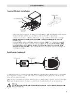
Headset Module Installation
• With the CA cable routed from the intercom, cut the cable to length at the headset module and slide
the bend relief grommet over the end of the CA cable as shown in the figure above.
• Attach a RJ-12 connector to the end of the cable –see Appendix B “RJ-12 Connector Assembly.”
Always make sure the printed side of the cable is facing the release tab on the RJ-12
modular plug.
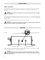
• Open the headset module assembly by removing the screws labeled “A” in the figure on page 6.
Install the plug and bend relief grommet as shown in the figure above.
If the CA cable is going
from the intercom to the headset module it MUST be inserted on the same side of the
HM-10 as the “Firecom” label.
Replace the headset module cover and mount the assembly with
the hardware provided.
Foot Switch (optional)
A radio Push-to-Talk (PTT) foot switch option is available from Firecom when a headset radio PTT is not desired.
Depressing the foot switch will initiate radio transmissions of the headset plugged into the headset module
where the foot switch is installed.
The foot switch is installed to the headset module using a CA cable and RJ-12 connector. You will need to open
the headset module and remove the plastic tab which covers the access hole to the second modular jack.
Warning
The CA cable from the intercom should always be plugged into the headset module on the
“Firecom” label side.
Summary of Contents for 110
Page 1: ...MODEL 110 RADIO COMMUNICATION SYSTEM INSTALLATION OPERATION MANUAL ...
Page 2: ......
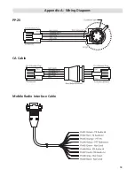
Page 15: ...13 Appendix A Wiring Diagrams PP 20 CA Cable Mobile Radio Interface Cable ...
Page 18: ......
Page 19: ......