


6
SYSTEM WIRING
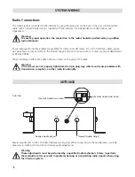
Power Connections
Power is wired to the unit using the power supply cable with in-line fuse (included). When routing the power
cable, the in-line fuse should be easy to access.
Warning
Before making power connections, make sure the power source is turned off.
Important
Use a dedicated ground for the (-) power connection. Do not ground to the chassis.
Important
We recommend connecting the intercom power to the same power busses as the 2-way radio.
CA Cable Routing
There are several important considerations when routing the CA cable:
• Do not bundle extra cable. The cable should be cut to length at installation, especially when radios
are used.
• Route CA cables away from hot surfaces including vehicle exhaust systems.
• When routing CA cables through bulkheads or other sheet metal, use a grommet in the hole to
prevent damage to the cable.
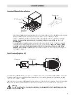
Headset Module Installation
The following steps are recommended for installing a HM-10 or PP-20 headset module.
• Identify where the headset module is to be mounted and use the module as a template to locate the
two mounting holes as shown in figure above. Drill two holes for the #6 hardware provided.
• If you are installing a PP-20 module, route the CA cable as outlined in
“CA Cable Routing”
on this
page and install an RJ-12 connector at the intercom end of the cable as outlined in Appendix B “RJ-12
Connector Assembly.”
Always make sure the printed side of the cable is facing the release tab
on the RJ-12 modular plug.
If you are installing an HM-10 module, continue with the following steps.
HM-10
PP-20
Summary of Contents for 110
Page 1: ...MODEL 110 RADIO COMMUNICATION SYSTEM INSTALLATION OPERATION MANUAL ...
Page 2: ......
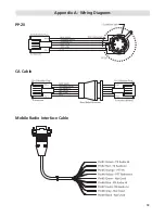
Page 15: ...13 Appendix A Wiring Diagrams PP 20 CA Cable Mobile Radio Interface Cable ...
Page 18: ......
Page 19: ......