


14
Appendix B - RJ-12 Connector Assembly
RJ Connector, 6 Position Plug Installation
To install the RJ-12 connector plug onto the flat CA cable:
1. Using the cutter blade on the crimping tool (labeled A, in figure 1), cut the CA
cable so the cut is clean and at a 90-degree angle to the side of the cable.
2. Fully insert one end of the CA cable between the stripping blades (labeled C,
in figure 1) until the end of the cable hits the stop (labeled B, in figure 1).
3. Squeeze the handles of the crimping tool together until the tool bottoms out.
4. While holding the handles together, pull the cable out of the tool.
5. The stripped insulation should expose approximately 3/16” of wire (figure 2).
6. Push a RJ-12 connector into the plug holder on the crimping tool (labeled D,
in figure 1) until the release tab on the plug locks into position.
7. Holding the cable so that the printed side of the cable is toward the release
tab on the plug, push the cable into the plug as far as it will go.
Note: Always make sure the printed side of the cable is facing the release
tab on the RJ-12 connector plug (figure 3). This ensures proper orientation
of the plug on each end of the cable.
8. Squeeze the tool handles completely together. You may feel the crimper
finish punching the contacts through the insulation on the wires.
9. Let the handles spring open.
10.Push down on RJ-12 connector release tab (figure 3) and remove the RJ-12
connector from the crimping tool.
11. Inspect the plug to ensure that the cable is held securely in place.
12. Repeat this procedure as necessary to install a RJ-12 connector plug on each
end of each CA cable.
Figure 1
RJ-12 Connector Plug
Crimping Tool
Figure 2
Stripped
CA Cable
Figure 3
RJ-12 Connector
Plug
Summary of Contents for 110
Page 1: ...MODEL 110 RADIO COMMUNICATION SYSTEM INSTALLATION OPERATION MANUAL ...
Page 2: ......
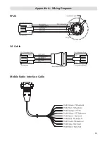
Page 15: ...13 Appendix A Wiring Diagrams PP 20 CA Cable Mobile Radio Interface Cable ...
Page 18: ......
Page 19: ......