


13
ES
PAÑO
L
FRANÇAI
S
DEUTSCH
EN
GLIS
H
IT
ALIANO
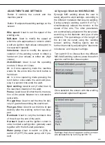
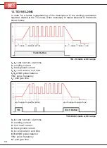
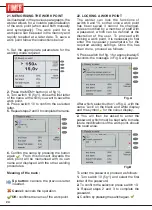
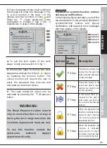
Start/End level:
Used to activate (ON) or
deactivate (OFF) the mode with the initial
and final current.
Start current:
Used to set the initial value as a
percentage of the welding current (e.g. 130%
implies Is=1,30xI1).
Start time:
Used in 2t mode to set the time
the initial current ls is applied
Ls->l1 slope:
Used to set the duration of the
current ramp from the initial level Is to the
welding current I1.
L1->le slope:
Used to set the duration of the
current ramp from the welding current I1 to
the final level Ie.
End current:
Used to set the final current as a
percentage of the welding current (e.g. 80%
implies If=0.80xI1).
End time:
Used in 2t mode to set the time
of application of the final current If.
Post-gas time:
Used to set the time of gas
delivery after the welding current has stopped.
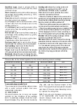
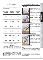
Please refer to the following table for the correct welding current settings:
WORKPIECE THICKNESS
WIRE DIAMETER
WELDING CURRENT
ARC
mm
mm
A
0.8 - 1.0
0.6 - 0.8
60 - 100
Short - Arc
1.5 - 2.0
0.8 - 1.0
80 - 120
Short - Arc
2.0 - 3.0
1.0 - 1.2
100 - 130
Short - Arc
3.0 - 4.0
1.2
120 - 200
Short - Arc
> 4.0
1
150 ÷ 200
Spray - Arc
> 4.0
1.2
200 ÷ 300
Spray - Arc
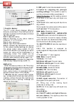
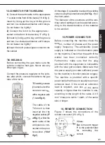
5.
MIG WELDING CONECTOR
The connector for the welding cables comes
with a quick connect system that uses
appropriate connectors.
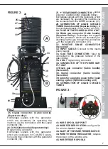
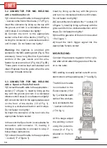
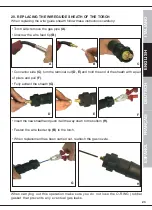
5.1. MIG TORCH
We would advise you to carry out regular
controls on the condition of the welding
torch; in particular, always check the nozz-
le/gas blowpipe (Fig. 4A) the wire feeder tip
(Fig. 4B), and the internal sheath of the
torch. These parts must be kept well-cleaned
and intact. If the wire stops threading correc-
tly. replace the wire guide.
N.B.
Each wire and diameter corresponds
to an appropriate wire feeder tip and
sheath. Always make sure you are using
the correct type.
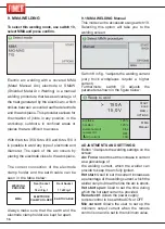
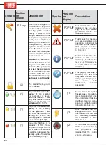
Cooling unit:
Allows the cooling control unit
(if fitted) to be switched ON or OFF or to be
automatically controlled (Auto), if available.
When the Auto mode is selected, the control
unit will be operated as follows:
•
When the machine is started or the control unit is
switched on, an operating test will be carried out to
check that the cooling system is working correctly,
then the control unit will be switched off;
• When the welding operations are started, the
control unit will be automatically switched on;
• When the welding operations are completed, the
control unit will remain switched on for a period
of time ranging from 30s to 10min, according to
the current supplied during the welding operation.
Remote:
Allows the synergy analogue remote
control to be switched ON or OFF.
Min level:
Allows the user to set up the synergy
parameter minimum value when the remote control
is switched on and is set to the lowest value, as a
% of the selected synergy point; if the value set
goes below the minimum synergy parameter
achievable by the machine for the selected curve,
the minimum synergy parameter will still be
followed.
Spot welding:
Used to set (if other than 0)
the maximum duration of the weld.
Pause:
Used to set (if other than 0) the duration
of the pause between two successive spot welds.
Burnback:
Allows the user to change the wire
burning time at the end of the welding operation.
Summary of Contents for King 350
Page 4: ...TARGA DATI NOMINAL DATA LEISTUNGSCHILDER PLAQUE DONÉES PLACA DE CARACTERÌSTICAS ...
Page 39: ...3 ...
Page 40: ...4 ...
Page 71: ...3 ...
Page 72: ...4 ...
Page 103: ...3 ...
Page 104: ...4 ...
Page 135: ...3 ...
Page 136: ...4 ...
Page 165: ...NOTE ...
Page 166: ...NOTE ...
Page 168: ......