16
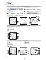
CONTROL HANDLEBAR ADJUSTMENT
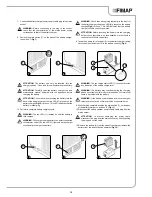
Correct adjustment of the control handlebar guarantees comfortable
use of the appliance. To adjust the control handlebar, proceed as
follows:
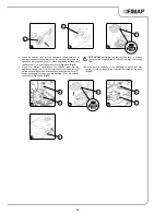
1. If the appliance is working, turn it off via the main switch (1) (
Fig.
1
).
2. Unblock the handlebar from the vertical position. Push the
steering column control stop lever (2) in the direction indicated
by the arrow (
Fig.2
) and turn the steering column control towards
you (
Fig.3
).
ATTENTION:
During this operation, do not rest your foot on
the appliance.
3.
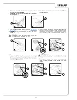
Turn the steering column control towards you until you find the
right position that allows you to operate the appliance comfortably.
4. Once the ideal position has been found, release the steering
column control stop lever (2) to lock the handlebar in position.
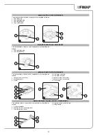
BATTERY CHARGE LEVEL INDICATOR
HOUR METER
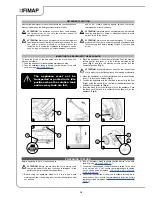
On the instrument panel of the machine there is a monitor indicating
(amongst other things) the battery charge status (B). The level of
battery charge is indicated via two symbols:
The percentage of charge: The numerical value which precedes the
% symbol
The graphic symbol: a line of luminous markings, each bar
corresponds to a % of the charge.
If the charge level reaches a certain value, the brush motor will switch
off automatically but you can still complete the drying operation.
On the machine's instrument panel there is a display indicating the
partial machine usage time (A). The top line shows the hours and
minutes of functioning.
If you push the dead man's lever, the hourglass symbol will begin to
flash and the appliance will begin to record the machine operation
time.
ATTENTION:
the flashing of the hourglass symbol is the only
sign that the hour meter is counting the machine operation
time.
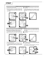
FILLING THE SOLUTION TANK
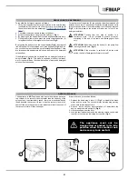
Proceed as follows to fill the solution tank with water:
1.
Take the machine to the usual place for filling the solution tank.
2. Do what is required to make sure the machine is in a safe
condition (see “
MACHINE SAFETY
”).
3. Disconnect the tank stop levers (1), and rotate in the direction
indicated by the arrow (
Fig.1
).
4. Remove the recovery tank from the appliance using the handles
(2). Gently lay the tank on the ground (
Fig.2
).
5. Remove the solution tank from the appliance using the handles
(3). Gently lay the tank on the ground (
Fig.3
).
1
2
1
3
2
OFF
1
3
2
1
2
3

