


Revised 08/03
6
APPLICATION NOTES FOR TGS2611
2-6
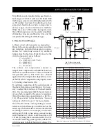
Preheating of final assembly
To stabilize the detector assembly before gas
testing, the minimum period for preheating final
assemblies should be 48 hours at room
temperature (20~25˚C). Be certain to maintain
clean atmospheric conditions for preheating.
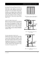
2-7
Gas test
Test all finished products in the target gas under
normal operating conditions. Keep the
atmospheric conditions in the chamber stable,
utilizing a user-defined standard test condition
which is based on applicable performance
standards and on anticipated usage for
detectors. Remove any traces of smoke,
adhesives, gases, or solvents from the chamber.
NOTE: Without testing after final assembly,
detectors have no guarantee of accuracy or
reliability.
2-8
Storage of finished products
Detectors should be stored in a clean air environ-
ment at room temperature. Avoid storage in
dirty or contaminated environments. Cautions
listed in Sec. 6-1.3 of “General Information for
TGS Sensors” should also be observed.
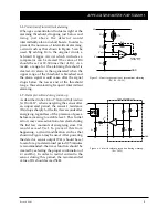
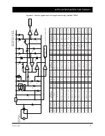
3. Anticipated Performance at 10%LEL of
Methane
When using the classified TGS2611 with Figaro’s
recommended R
L
for 10%LEL (Table 1) and
temperature compensated circuit design (Figure
2), typical alarm tolerances for 10%LEL of
methane such as those shown in Figure 9 are
expected. Each R
L
classification contains a range
of tolerance as exemplified by the alarming
range labelled as ‘standard conditions’ (i.e. these
conditions are well-controlled). When factoring
in the additional effects of environmental
extremes and the allowable variation in circuit
conditions, the resulting alarming range would
be typified by the range labelled as ‘operating
conditions’. However, in actual usage, alarm
thresholds may vary since the threshold is also
affected by factors such as the tolerances of the
thermistor and/or other components, load
resistor value, test conditions, and heat
generation inside the detector enclosure. As a
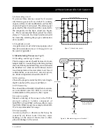
Figure 9 - Expected performance of methane detectors
with classified TGS2611 & recommended R
L
for 10% LEL
(
refer to Table 3 for test conditions
)
d
n
a
e
r
u
t
a
r
e
p
m
e
T
y
t
i
d
i
m
u
h
d
r
a
d
n
a
t
S
s
n
o
i
t
i
d
n
o
c
0
2
±
5
6
,
C
˚
2
±
H
R
%
5
g
n
i
t
a
r
e
p
O
s
n
o
i
t
i
d
n
o
c
H
R
%
5
9
~
0
3
,
C
˚
0
4
~
0
1
-
t
i
u
c
r
i
C
n
o
i
t
i
d
n
o
c
d
r
a
d
n
a
t
S
s
n
o
i
t
i
d
n
o
c
0
.
5
=
c
V
±
C
D
V
1
0
.
0
0
.
5
=
H
V
±
C
D
V
5
0
.
0
g
n
i
t
a
r
e
p
O
s
n
o
i
t
i
d
n
o
c
0
.
5
=
c
V
±
C
D
V
2
.
0
0
.
5
=
H
V
±
C
D
V
2
.
0
r
o
i
r
p
g
n
i
n
o
i
t
i
d
n
o
C
t
s
e
t
o
t
≥
s
r
u
o
h
8
4
Table 3 - Test conditions for measuring
performance of methane detectors as shown in Figure 9
3
4
5
6
7
8
9 10
20
15
30
under std
test conditions
under operating conditions
at recommended circuit condition
Alarming point (%LEL)
25


