Revised 08/03
4
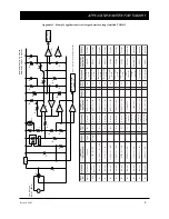
APPLICATION NOTES FOR TGS2611
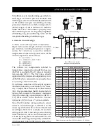
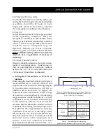
Figure 5 - Circuit for prevention of intermittent alarming
(R
D
/R
C
= 20~30)
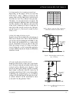
Figure 6 - Circuit for alarm prevention during warmup
(R
F
> 5k
Ω
)
1-6
Prevention of intermittent alarming
When gas concentration fluctuates right at the
alarming threshold, dropping just below and
rising just above, the detector would
intermittently alarm in short bursts. In order to
prevent the nuisance of intermittent alarming,
a circuit such as that shown in Figure 5 can be
used. By adding R
D
to the original circuit, a
Schmidt trigger circuit which includes a
comparator can be created (the value of R
D
should be set at 20-30 times that of Rc). As a
result, a range for the alarming threshold is
created. An alarm is then generated when the
upper range of the threshold is breached and
the alarm signal would cease after the signal
drops below the lower end of the threshold
range, thus eliminating frequent intermittent
alarming.
1-7
Alarm prevention during warm-up
As described in Sec. 2-6 of “
Technical Information
for TGS2611
”, when energizing the sensor after
an unpowered period, the sensor’s resistance
(Rs) drops sharply for the first few seconds after
energizing, regardless of the presence of gases,
before recovering to a stable level. This ‘initial
action’ may cause activation of an alarm during
the first few moments of energizing since V
RL
would exceed Vref. To prevent this from
happening, a circuit modification such as that
shown in Figure 6 may be used. After powering
the detector, sensor output (V
RL
) should be set
to zero for a pre-determined period (2.5 minutes
is recommended--the timer function should be
created by selecting the proper combination of
C
3
and R
11
). In order to restrict current to the
sensor during this period, the recommended
value of R
F
should exceed 5k
Ω
.
+
-
V
REF
V
RL
R
D
R
C
GND
V
C
R
A
R
B
Alarm signal
(Active = 'L')
R
TH
R
L
+
-
V
C
V
RL
GND
+
R
F
2.5 min. time delay circuit
R
10
C
3
R
9
R
11
D
5


