background image

page 8 of 12

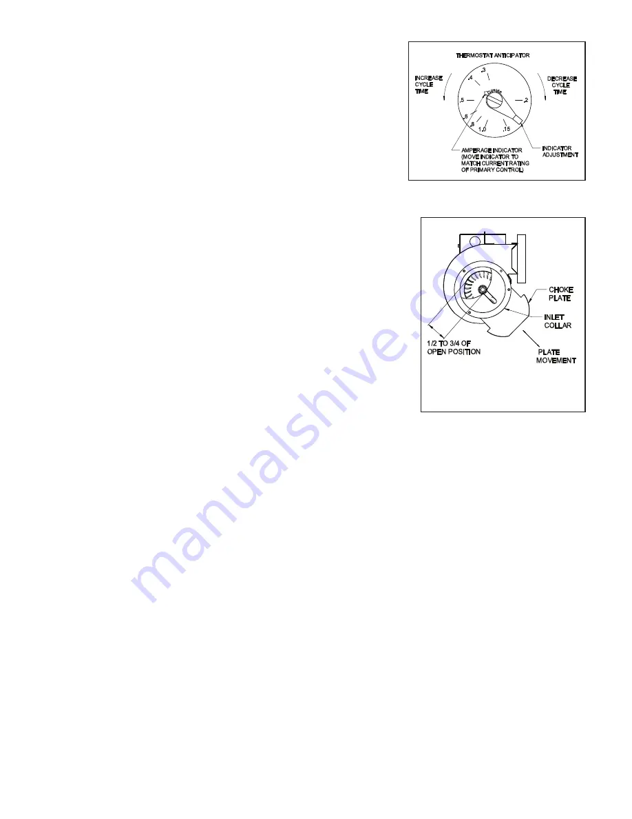
ADJUSTING THERMOSTAT ANTICIPATOR

If connecting the Power Venter system to a gas appliance with a thermostat 
anticipator, refer to the following to make adjustments. Disconnect one 
side of the thermostat circuit at the gas valve or burner control, and 
connect an ampere meter into the circuit. With the system running, take 
an amperage reading on the circuit. Check the nameplate or instructions 
for the thermostat to obtain the proper amperage level. Adjust amperage 
level by moving the anticipator lever. Reconnect the thermostat to the 
gas valve and start the system operating. Time the burn cycles and 
adjust as follows; To make the cycle time longer, increase the amount on 
the anticipator (Example: .45 to .5 Amps); to decrease cycle time, reduce 
the amount on the anticipator (Example: .45 to .3 Amps). (See Figure 8)

AIR FLOW ADJUSTMENTS

1. To properly adjust the venter air fl ow, loosen the inlet ring screws and 

open the choke plate approximately 

1

2

 to 

3

4

 open. (See Figure 10) Start the 

heating appliance following the manufacturer specifi ed procedure, and 
set the thermostat to call for heat.

2.  After the system has operated for several minutes to stabilize the exhaust 

gas temperature, check for air fl ow at the draft hood or the heating 
appliance outlet using a velocity meter, draft meter, or match test 
procedure.

3.  Adjust the venter choke plate inward or outward to obtain the minimum draft 

necessary to maintain venting. Then increase the draft slightly (approximately 
10% over minimum fl ow rate) to ensure proper venting during any variations 
in venter performance, such as wind load or house depressurization.

4.  Secure the choke plate into position by tightening the screws on the 

inlet collar (See Figure 9)

GENERAL INSTALLATION INSPECTION

Follow recommended procedures for safety inspection of a heating appliance in accordance with the National Fuel 
Gas Code ANSI Z223.1. The following procedure will help in evaluation of the venting system. It is intended as a 
guide to aid in determining that the appliance is properly installed and is in a safe condition for continuous use. 
This is a generalized procedure which cannot anticipate all situations. Accordingly, in some cases deviation from 
this procedure may be necessary to determine safe operation of the equipment. If it is determined that a condition 
which could result in unsafe operation exists, the appliance should be shut off  and the owner advised of the unsafe 
conditions. Corrections must be made prior to allowing continuous operation. The following steps should be taken 
in making a safety inspection.

1.  Visually inspect the venting system for proper size and determine that there is no blockage, restriction, leakage, 

corrosion, or other defi ciencies which could cause unsafe operation.

2. To the extent possible, close all building doors, windows, and all doors to the room in which the heating 

appliance is located. Turn on clothes dryers and any exhaust fans so that they operate at maximum speed. Do 
not operate a summer exhaust fan. Also close all fi replace dampers. If after completing steps 3 through 7 it is 
believed that suffi

  cient combustion air is not available, refer to the National Fuel Gas Code ANSI Z223.1 or any 

local codes for proper guidelines.

3.  Place the appliance being inspected into operation. Follow the lighting instructions and adjust the thermostat 

so that the heating appliance will operate continuously.

4.  Determine that the burner is operating properly and that the main burner ignition functions satisfactorily, by 

interrupting the electrical power of the appliance in any safely convenient manner. Test the burner safety device 
to determine if it is operating properly by extinguishing the pilot or disconnecting the fl ame safety circuit.

Figure 8

Figure 9

P/N 46246300 Rev M 04/20

Summary of Contents for PVG-100

Page 1: ... with pre wired integral 24 VAC Relay Timer factory set Draft Proving Switch and direct access Terminal Blocks 1 Installation Instruction Sheet OPTIONAL SYSTEM COMPONENTS NOT INCLUDED Side Wall Vent Hood Spill Switches Barometric Draft Control CONTENTS PAGE System Operation 2 Power Venter Sizing 3 4 Installation Safety Instructions 4 5 Installation of Power Venter 5 6 General Wiring Instructions 7...

Page 2: ...run the power venter for a period of time after the burner has shut off to purge remaining flue gases UNIT SPECIFICATIONS Table 1 UNIT DIMENSIONS INCHES ELECTRICAL RATINGS MODEL H W D I O VAC Hz RPM WATT AMP TP PVG 100 7 5 10 0 7 0 4 4 115 60 3000 145 2 1 YES PVG 300 7 5 11 5 7 0 4 4 115 60 3000 145 2 1 YES PVG 600 8 75 12 0 8 5 5 5 115 60 3000 167 1 5 YES Inlet and outlet diameter Thermally prote...

Page 3: ...H IN FEET 1 Calculate the total equivalent feet for each type of fitting used in the venting system from the following chart 2 Calculate the total amount of feet for the straight lengths of vent pipe 3 Add the equivalent feet for the fittings with the total amount of feet of straight lengths Table 3 Reducer or increaser ratio d D small diameter divided by the larger diameter See Figure 3 Example 4...

Page 4: ...nded by the National Fuel Gas Code ANSI Z223 1 or refer to the General Installation Inspection section of this manual 3 Plan the vent system layout before installation to avoid the possibility of accidental contact with concealed wiring or plumbing inside walls 4 Single wall vent pipe may be used to join an appliance to the venting system but if proper clearances cannot be maintained from combusti...

Page 5: ...stems shall not be less than 7 above grade when located adjacent to public walkways b A venting system shall terminate at least 3 above any forced air inlet located within 10 c The venting system of other than a direct vent appliance shall terminate at least 4 below 4 horizontally from or 1 above any door window or gravity air inlet into the building d The vent termination of a direct vent applian...

Page 6: ...regulate any draft fluctuations during operation 1 Use approved vent connectors to join the heating appliance outlet to the venter inlet securing each joint with sheet metal screws or equivalent means of fastening when required 2 Seal all pipe joints on the outlet side of the venter with a high temperature silicone adhesive or equivalent Test the vent connections for leaks by using a soap solution...

Page 7: ...r circuit breaker rated at 15 amperes Prevent wiring contact with any heat source Wire the venter in accordance with the National Electrical Code and applicable local codes Refer to Diagram B for proper wiring specifications Diagram B 3 Wire the switch into the low voltage thermostat circuit Refer to the appropriate wiring diagram in this manual 4 After installation check the amperage through the ...

Page 8: ...a heating appliance in accordance with the National Fuel Gas Code ANSI Z223 1 The following procedure will help in evaluation of the venting system It is intended as a guide to aid in determining that the appliance is properly installed and is in a safe condition for continuous use This is a generalized procedure which cannot anticipate all situations Accordingly in some cases deviation from this ...

Page 9: ...nce a year motor should rotate freely To prolong the life of the PVG 600 motor it must be lubricated with six drops of SWG Superlube Part 46226200 annually The PVG 100 and PVG 300 have sealed ball bearings and therefore do not need to be oiled Blower Wheel Inspect the blower wheel annually to clear any soot ash or coating which inhibits either rotation or air flow Remove all foreign materials befo...

Page 10: ...city of the venter selected b A CK 41 Control Kit must be added to the system to properly control the venter when common venting an additional 24 VAC furnace or boiler Tee the draft tube on the PVG unit to connect to the air pressure switch on the Control Kit Refer to Diagram D for wiring instructions PV SERIES POWER VENTER VERTICAL VENTING OPTION Diagram C illustrates correct and incorrect instal...

Page 11: ...L1 L2 TERMINAL STRIP IN 24VAC CONTROL KIT ON SECOND APPLIANCE APPLIANCE CONNECTIONS L1 L2 GAS PRESSURE SWITCH ON MILLIVOLT APPLIANCE PVG WIRING FOR MULTIPLE 24VAC APPLIANCES PVG WIRING FOR MULTIPLE 24VAC APPLIANCES VENTING SYSTEM OPERATIONAL INFORMATION Date Heating appliance BTU HR input Gas valve operation pressure Vent system draft above draft hood or below barometric draft control CO2 measurem...

Page 12: ...m ventCool Field Controls Technical Support Field Controls Technical Support 1 800 742 8368 1 800 742 8368 fieldtec fieldcontrols com fieldtec fieldcontrols com This manual may be downloaded and printed from the Field Controls website www fieldcontrols com This manual may be downloaded and printed from the Field Controls website www fieldcontrols com WARRANTY WARRANTY For warranty information abou...

Reviews: