


Reproduction forbidden without Fibocom Wireless Inc. written authorization - All Rights Reserved.
FM350-GL Hardware Guide
Page 21 of 59
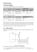
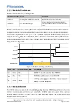
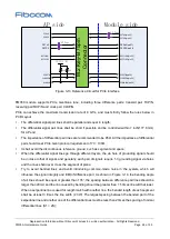
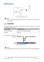
Figure 3-4 Circuit for module start-up controlled by AP
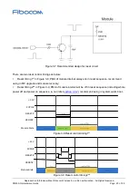
3.3.1.2
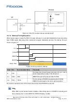
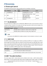
Start-up Timing Sequence
When power supply is ready, the PMU of module will power on and start initialization process by pulling
high FCPO# signal. After about 20s, module will complete initialization process. The start-up timing is
shown in Figure 3-5:
+3.3V
PERST#
t
pr
RESET#
t
on
1
Module State
Initialization
Activation(AT Command Ready)
FCPO#
t
on
2
typical 20s
OFF
Figure 3-5 Timing control for start-up
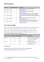
Index Min.
Recommended Max.
Comments
t
pr
0ms
-
-
The delay time of power supply rising from 0V up to 3.3V.If
power supply always ready, it can be ignored
t
on1
20ms
20ms
-
RESET# should be de-asserted after FCPO#
t
on2
50ms
100ms
-
The time delay of PERST# de-asserted after FCPO#,
PERST# must always be the last to get de-asserted
The minimum detection time of PCIe link is about 23ms after PERST# de-asserted.
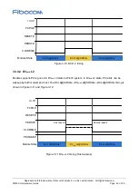
Note
:
When USB is used as data transfer interface, follow timing above in PERST# connecting with
host, otherwise don’t control PERST# in PERST# floating condition.


