background image

3 Web Configuration Guide

Table 3-25

Parameters for Port Forwarding (Continued)

Item

Description

Private Port

The range of the LAN ports for forwarding. If only one port exists, enter

the same port number.

Protocol

The protocol used for the port to forward data packets. The options

include ALL, TCP and UDP.

Enable

Enables or disables the rule.

3.5.4

NAT

NAT allows the conversion between intranet IP addresses and public network IP

addresses. NAT converts a great number of intranet IP addresses into one or a

small number of public network IP addresses, so as to save the resource of public

network IP addresses.

The NAT configuration below can take effect only when the NAT function

is enabled in

Network

BroadBand Settings

Internet Settings

.

1.

Select

Application

in the navigation bar and select

NAT

NAT

in the left link

bar. Then click

Add

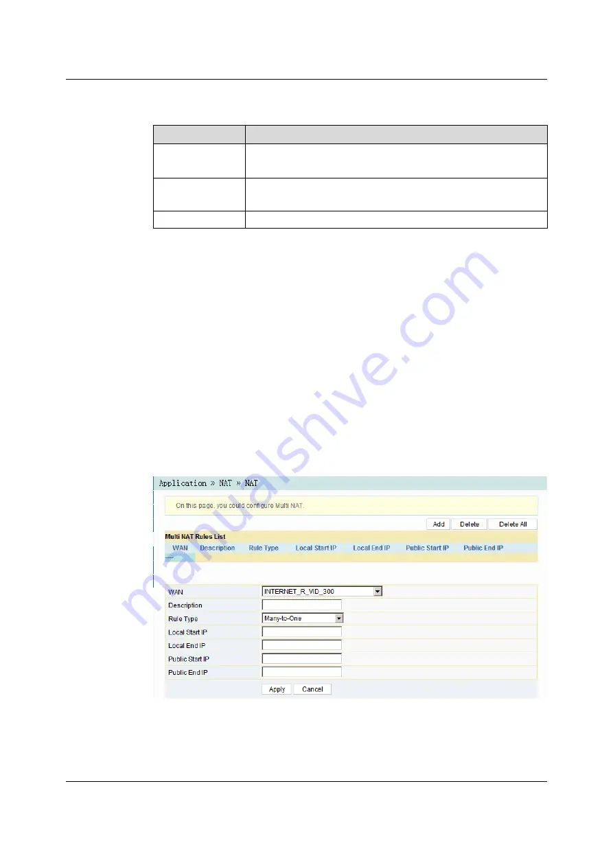
to open the NAT rule list configuration page, as shown in

Figure 3-46.

Figure 3-46

NAT

Version: A

75

Summary of Contents for HG6143D

Page 1: ...Version A HG6143D Product Manual FiberHome Telecommunication Technologies Co Ltd April2020...

Page 2: ...ocal sales representative service representative or distributor for any help needed at the contact information shown below Fiberhome Telecommunication Technologies Co Ltd Address No 67 Guanggu Chuangy...

Page 3: ...nt are used for identification purposes only and are trademarks or registered trademarks of their respective holders All rights reserved No part of this document including the electronic version may b...

Page 4: ...ediately u Use the power supply adapter provided in the package only Using other adapters may cause equipment damage or operation failures u Install the equipment in a well ventilated environment with...

Page 5: ...1 Appearance 6 2 4 2 Product Characteristics 11 2 4 3 Functions and Features 12 2 4 4 Technical Specifications 17 3 Web Configuration Guide 18 3 1 Local Login to the Web Configuration GUI 19 3 2 Statu...

Page 6: ...l Signal Status Indicator LED Blinking 88 4 4 Ethernet Interface Status Indicator LED Extinguished 88 4 5 Failing to Detect the ONT Using Wi Fi 89 4 6 Failing to Access Local Web Login GUI and Failing...

Page 7: ...4 10 Test of Voice Service Failed 90 5 Standards and Protocols 91 Appendix A Abbreviations 93...

Page 8: ......

Page 9: ...to handle common problems encountered during product operations and service tests including abnormal statuses of indicator LEDs failing to access the Internet failure of voice service tests etc Stand...

Page 10: ...2 Product Introduction 2 Version A Product Positioning Product Specification Interface Specifications Introduction to the HG6143D...

Page 11: ...es users with communication and entertainment services in the form of data voice video and so on to meet the integrated access demand of families and small scaled enterprises The figure below shows th...

Page 12: ...ansmission distance 20 km Central wavelength Tx 1310 nm Rx 1490 nm Optical power Extinction ratio Higher than 10 dB Receiving sensitivity Maximum overload optical power 8 dBm 2 3 2 LAN Interface Item...

Page 13: ...de PCM 2 3 4 Wi Fi Interface Item Specification Standard compliance IEEE 802 11 a b g n ac Operating band 2 4GHz 5GHz Specifications Four SSIDs and 13 working channels for the 2 4 GHz band four SSIDs...

Page 14: ...A Introduction to the HG6143D Appearance This section describes the appearance of the HG6143D including the overall look interfaces buttons and indicator LEDs The overall look of the HG6143D is shown...

Page 15: ...ersion A 7 Interfaces and buttons of the HG6143D are located on the rear side and bottom panels of the equipment Figure 2 2 Figure 2 3 and Figure 2 4 show the rear panel side panel and bottom panel re...

Page 16: ...Figure 2 3 Side Panel of the HG6143D Figure 2 4 Bottom Panel of the HG6143D Table 2 3 describes the interfaces and buttons on the HG6143D 8 Version A HG6143D Product Manual...

Page 17: ...data encryption PON Fiber interface Connects with the optical fiber for uplink access Indicator LEDs Indicator LED Meaning Color Status Status Description Power Power status indicator LED Green ON Th...

Page 18: ...S is in use for relevant negotiation OFF WPS is not enabled or the Wi Fi terminal is not connected to the ONT USB indicator LED Green ON The USB is connected OFF The USB is not connected LAN1 to LAN4...

Page 19: ...g n ac to help you set up a safe and reliable wireless network u Compatible with IEEE 802 11 a b g n ac and authenticated by Wi Fi Alliance with good compatibility with other WLAN devices u Supports e...

Page 20: ...nd ACL rules to guarantee safe operation of the equipment 6 Remote Automatic Service Provisioning Maintenance and Management u Supports configuring the user defined upgrade policies through the networ...

Page 21: ...NTsupports no less than 64 GEM ports Supports eight T CONTs DBA Supports DBA in the SR and NSR modes Supports DBA Piggy back DBRu Mode 0 FEC Supports bi directional FEC downlink FEC decoding and uplin...

Page 22: ...s fast leave Supports translation transparent transmission and stripping of the multicast VLAN tags Supports VLAN translation for the uplink multicast protocol messages Supports filtering the downlink...

Page 23: ...wo POTS subscribers Supports static and dynamic jitter buffer Supports DTMF detection Supports RFC 2833 for transmitting receiving DTMF Supports RTP RTCP RFC 3550 WLAN Supports 802 11b 802 11g 802 11n...

Page 24: ...orts local service configuration query and software upgrade based on the Web page Supports management of OMCI configurations and queries Supports query of the ONToptical module information Supports Ty...

Page 25: ...149 mm H W D Wall mounting hole distance 121 mm Weight About 339 g Power supply parameters DC DC 12 V 1 5 A Power consumption parameter Static power consumption 7 W Maximum power consumption 17 W Envi...

Page 26: ...system For details please refer to the relevant OLTconfiguration guide Local Login to the Web Configuration GUI Status Network Security Application Management 18 Version A This chapter introduces the...

Page 27: ...n GUI Prerequisites u The ONT has been connected to the computer correctly u The user computer is started normally u The ONT is started normally Press down the ONT s power button If the power indicato...

Page 28: ...e ONT Factory default value u IP address 192 168 1 1 u Subnet mask 255 255 255 0 Note Some operators require customized management IP address so that the default management IP address may be different...

Page 29: ...Panel and click Network and Sharing Center b Click Local Area Connection to bring up the Local Area Connection Status dialog box and click Properties c In the Local Area Connection Properties dialog...

Page 30: ...In the Internet Protocol 4 TCP IPv4 Properties dialog box that appears set the IP address and subnet mask of the computer For details of the parameters see Table 3 1 22 Version A HG6143D Product Manua...

Page 31: ...ork Connection to access the network connection window b Right click Local Connection and select Properties from the shortcut menu to bring up the Local Connection Properties dialog box c Double click...

Page 32: ...ox Access the Web GUI after the password is authenticated Caution The system will log out automatically if no user operation is detected in five minutes Layout of the Web Configuration GUI The Web con...

Page 33: ...s u The administrator can view and configure all the node items in the Web GUI u The common users can view and configure only part of the node items The following lists the key nodes available for com...

Page 34: ...rmation 3 2 2 Wireless Network Status View the information about the wireless network such as network mode frequency channel SSID count of wireless packets and list of Wi Fi clients 3 2 2 1 Wireless N...

Page 35: ...he 5G Wireless Network Select Status in the navigation bar and then select Wireless Status 5G Wireless Status in the left link bar to view the information of the 5G wireless network such as network mo...

Page 36: ...st of client ends connected to the ONT wireless network as shown in Figure 3 5 Figure 3 5 WIFI User List 3 2 3 WAN Side Status Select Status in the navigation bar and then select Wan Status Wan Status...

Page 37: ...Status Lan Status in the left link bar to view the information such as the IP address and subnet mask of the LAN side as shown in Figure 3 7 Figure 3 7 LAN Side Status 3 2 4 2 DHCP User List Select S...

Page 38: ...ch as the Tx optical power Rx optical power and working temperature as shown in Figure 3 9 Figure 3 9 Optical Power Status 3 2 6 Voice Status Select Status in the navigation bar and select VoIP Status...

Page 39: ...rameters Configure the parameters of the 2 4G wireless network such as the switch network mode domain frequency bandwidth and frequency channel 1 Select Network in the navigation bar and select Wlan S...

Page 40: ...nnel used for communication between the wireless access point and the wireless station The options includes AutoSelect and Channel1 to Channel13 The default setting is AutoSelect Guard Interval The wi...

Page 41: ...ecurity cannot be guaranteed This mode is not advisable u SHARED This mode is based on the WEP encryption protocol where the same key is configured for the wireless access client end and equipment sid...

Page 42: ...26 characters Note Pressing the Apply button will validate a single SSID choice configuration item If you do not click Apply after modifying the SSID 1 setting the modification will not take effect If...

Page 43: ...ansmit power of the wireless signal A larger value indicates a wider signal coverage Number of WIFI Connections The maximum number of client ends supported by the SSIDs 3 3 1 4 5G Basic Parameters Con...

Page 44: ...ptions include 802 11a 802 11a n and 802 11a n ac The default setting is 802 11a n ac Domain Select your region Frequency Bandwidth The width of wireless band The options include 20MHz 40MHz 20MHz 40M...

Page 45: ...rity mode and algorithm For details of the parameters see Table 3 3 3 Click Apply to save and apply the configuration Note Pressing the Apply button will validate a single SSID choice configuration it...

Page 46: ...ent ends For details of the parameters see Table 3 4 3 Click Apply to save and apply the configuration 3 3 1 7 WPS Configuration left link bar to open the WPS settings page as shown in Figure 3 17 38...

Page 47: ...Then click Connect 4 Select Please turn on the button of the equipment and press down the WPS button on the ONT Then press down the WPS button or the WPS software key on the client end 4 Wait until th...

Page 48: ...LAN The default setting is 255 255 255 0 IPv6 Prefix The IPv6 gateway address including a prefix of 64 bits The default value is fe80 1 64 Managed Flag Select whether to distribute the IPv6 addresses...

Page 49: ...her Config Flag is selected otherwise the IP address or DNS information cannot be distributed The server is enabled by default Start IPv6 Address The starting address ID of the address pool for distri...

Page 50: ...is set to INTERNET or OTHER u Route the Layer 3 router connection mode This connection mode can be used when the service type is set to INTERNET or OTHER VLAN ID Sets the VLAN ID of the WAN connection...

Page 51: ...ort IP Mode The options include IPv4 IPv6 IPv4 and IPv6 u Users need to WAN IP Mode Sets the IP address obtaining mode at the WAN side of the ONT The options include DHCP static and PPPoE u DHCP Obtai...

Page 52: ...static IPv6 address at the WAN side provided by the ISP This item should be set when the IP Mode is set to IPv4 IPv6 or IPv6 and the WAN IP Mode is set to static IPv6 Prefix Length Enter the static IP...

Page 53: ...Parameters for the DHCP Server Item Description Type Enables or disables the DHCP server u Server Enables the DHCP server The ONTcan dynamically distribute IP addresses to user terminals u Disable The...

Page 54: ...The starting IP address of the network segment distributed to the Option 60 property terminal by the DHCP server This item should be configured when the Option 60 field of the DHCP server is enabled O...

Page 55: ...the LOID user name This item is configurable when the ONT uses the LOID authentication mode Logic Password Sets the LOID password Password Auth Sets the authentication password when the ONT is authent...

Page 56: ...WAN Name The WAN port passed by the static routing Select a valid WAN port 3 3 7 Voice Configuration This section introduces how to configure the key parameters basic parameters advanced settings digi...

Page 57: ...Parameters for Voice Service Item Description VoIP Protocol The voice protocol type The options include SIP and H 248 The default setting is SIP Port Enable or disable the VoIP port 3 3 7 2 Basic Par...

Page 58: ...ameters for Voice Service Item Description VoIP Protocol The VoIP protocol type configured in Key Parameters VoIP Username The VoIP username VoIP Password The VoIP password Telephone Number The teleph...

Page 59: ...The CVLAN ID The value range is 1 to 4095 CVLAN Priority The CVLAN priority The value range is 0 to 7 and the default setting is 0 SVLAN ID The SVLAN ID The value range is 1 to 4095 SVLAN Priority Th...

Page 60: ...e and apply the configuration Table 3 13 Advanced Parameters for Voice Service Item Description RFC2833 PT Value The default PT value in RFC2833 The value range is 0 and 96 to 127 RFC2198 PT Value The...

Page 61: ...cal port The value range is 1024 to 65535 and the default setting is 5060 Echo Cancel Enable or disable the echo suppression The default setting is Enable Silence Suppression Enable or disable the sil...

Page 62: ...The value range is 120 to 65535 s and the default setting is 3600 Short Digit Timer The timeout period set for the short timer The value range is 1 to 254 s and the default setting is 4 Long Digit Tim...

Page 63: ...etting is 30 Avalanche Timer The timeout period set for the avalanche timer The value range is 1 to 254 s and the default setting is 30 Sliding Spring Time The sliding spring time The value ranges fro...

Page 64: ...P packetization period The value range is 10 to 60 ms 3 4 Security This section introduces how to configure the firewall remote control route QoS ACL configuration dynamic DoS and HTTPS in the Web GUI...

Page 65: ...ewall as required 3 Click Apply to save and apply the configuration 3 4 1 2 IPv4 Filtering Allow or forbid the incoming or outgoing flow of the IP packets meeting the filtering criteria After the fire...

Page 66: ...e allowed to pass u Black List indicates that the data complying with the rules in the filtering rule table will not be allowed to pass Click the Apply button below to apply the settings Direction Set...

Page 67: ...otocol is set to TCP or UDP Protocol The protocol type including TCP UDP ICMP and ALL 3 4 1 3 IPv6 Filtering Allow or forbid the IPv6 packets meeting the filtering criteria to be transmitted from the...

Page 68: ...direction of the filtering rule u LAN WAN uplink direction u WAN LAN downlink direction Src IPv6 Enter the IPv6 address at the LAN side if the direction is set to LAN WAN Enter the IPv6 address at th...

Page 69: ...ring Parameters Item Description Enable Enables or disables the URL filtering function Click the Apply button below to apply the settings URL Blacklist Whitelist Select the filtering mode The white li...

Page 70: ...dress in the DHCP mode to prevent DOS attacks After the firewall is enabled the pre set rules will take effect 1 Select Security in the navigation bar and select Firewall DHCP Filtering in the left li...

Page 71: ...ess to obtain an IP address through the DHCP u Black List indicates forbidding the device configured with the MAC address to obtain an IP address through the DHCP MAC Address The MAC address of the us...

Page 72: ...ation bar and select Firewall MAC Filtering in the left link bar and then click Add to open the MAC address filtering table configuration page as shown in Figure 3 34 Figure 3 34 MAC Address Filtering...

Page 73: ...Start Time The starting time of the filtering rule End Time The ending time of the filtering rule Enable Enables or disables this filtering rule The options include Disable and Enable 3 4 1 8 IPv6 MA...

Page 74: ...pply the settings IPv6 MAC Filtering Blacklist Whitelist Select the filtering mode The white list and black list modes are configured globally and cannot be enabled simultaneously u White List indicat...

Page 75: ...isabled the PCs in the Internet cannot access the Web GUI of the ONT using the IP addresses at the WAN side when enabled the PCs in the Internet can access the Web GUI of the ONT using the aforesaid I...

Page 76: ...the left link bar to open the anti DoS attack configuration page as shown in Figure 3 41 Figure 3 41 Dynamic DoS 2 Select to Enable or Disable the anti dos attack function as required 3 Click Apply to...

Page 77: ...e and apply the configuration 3 5 Application This section introduces how to configure the VPN DDNS port forwarding NAT UPnP DMZ and network diagnosis on the Web GUI 3 5 1 VPN Set whether to enable th...

Page 78: ...in Figure 3 44 Figure 3 44 DDNS Settings 2 Configure parameters relevant to DDNS according to the requirement For details of the parameters see Table 3 24 3 Click Apply to save and apply the configur...

Page 79: ...o open the port forwarding configuration page as shown in Figure 3 45 Figure 3 45 Port Forwarding 2 Configure parameters relevant to port forwarding according to the requirement For details of the par...

Page 80: ...nversion between intranet IP addresses and public network IP addresses NATconverts a great number of intranet IP addresses into one or a small number of public network IP addresses so as to save the r...

Page 81: ...WAN connection bound with the NAT rule Description The NAT rule name Rule Type Select the NATconversion mode It is advisable to select One to One or Many to One Local Start IP The starting IP address...

Page 82: ...ameters according to the requirement For details of the parameters see Table 3 27 3 Click Apply to save and apply the configuration Table 3 27 Parameters for DMZ Configuration Item Description DMZ Ena...

Page 83: ...gnosis page as shown in Figure 3 49 Figure 3 49 Network Diagnosis 2 Enter the destination IP address to be tested in the Destination Address box and click Ping or Traceroute to test The test result wi...

Page 84: ...User management includes user account management and maintenance account management 3 6 1 1 User Account Management Users can add or delete a common user account or modify the password of a common us...

Page 85: ...dify the username and password of the current account 1 Select Management in the navigation bar Select Account Management Maintenance Account from the left link bar to open the maintenance account man...

Page 86: ...gement in the navigation bar Select Device Management Restore from the left link bar to open the configuration restoring page as shown in Figure 3 53 Figure 3 53 Restoring the Configuration Data 2 Cli...

Page 87: ...ct the device software version to be upgraded and click Open to upgrade the ONTsoftware 3 When the upgrade succeeds the page will prompt for device rebooting Click Reboot After rebooting the device wi...

Page 88: ...Username The FTP username Password The FTP password Localhost IP The local IP address File Name The existing file name of the ONT 3 6 2 5 FTP Server With the FTP server function of the ONTenabled user...

Page 89: ...58 Device Reboot 2 Click Reboot and click OK in the alert box that appears and wait for the device to reboot Caution Save the configuration data before rebooting the device to prevent loss of the data...

Page 90: ...IP address of the active NTP server Second NTP Server Enter the IP address of the standby NTP server Time Zone Select the time zone according to the location of the device Current Time When NTP Check...

Page 91: ...Select Management in the navigation bar Select Log Log from the left link bar to open the log information page as shown in Figure 3 60 Figure 3 60 Log 86 Version A HG6143D Product Manual...

Page 92: ...LED Extinguished Optical Signal Status Indicator LED Blinking Ethernet Interface Status Indicator LED Extinguished Failing to Detect the ONT Using Wi Fi Failing to Access Local Web Login GUI and Faili...

Page 93: ...eck whether the ONT has obtained the ISP authorization 4 Check whether the optical interface is normal if not replace the device 4 3 Optical Signal Status Indicator LED Blinking Handle the problem acc...

Page 94: ...eless terminal such as computer and telephone is enabled 3 Adjust the position of the ONT to reduce the barriers on the wireless channel such as walls and make sure the distance between the ONTand the...

Page 95: ...Normal Range Contact the personnel in the network management center to check whether the bandwidth profile is configured correctly and bound to the ONT 4 10 Test of Voice Service Failed Handle the pr...

Page 96: ...ged Local Area Networks Amendment 4 Provider Bridges IEEE 802 1ad IEEE Standard for Local and Metropolitan Area Networks Virtual Bridged Local Area Networks Amendment 4 Provider Bridges IEEE 802 1x 20...

Page 97: ...68 Digital network echo cancellers Multicast IETF RFC 2236 Internet Group Management Protocol Version 2 IETF RFC 3376 Internet Group Management Protocol Version 3 IETF RFC 4541 Considerations for Inte...

Page 98: ...aintenance FEC Forward Error Correction TDMA Time Division Multiple Access PLOAM Physical Layer Operations Administration and Maintenance OMCI ONU Management and Control Interface T CONT Transmission...

Page 99: ...Networks MTU Maximum Transmission Unit PPPoE Point to Point Protocol over Ethernet DTMF Dual Tone Multi Frequency VPN Virtual Private Network DDNS Dynamic Domain Name Server FTP File Transfer Protoco...

Page 100: ...en do you use the documentation Frequently Rarely Never Other please specify 2 When do you use the documentation in starting up a project in installing the product in daily maintenance in trouble shoo...

Page 101: ...inion on the Figures in the documentation Beautiful Unbeautiful your advice Practical Unpractical your advice 10 What is your opinion on the layout of the documentation Beautiful Unbeautiful your advi...

Reviews: