8
Mounting and installation
8.1 Installing the angle seat valve
Prerequisites
– The piping system is unpressurised and no medium flows in it
– Lines are clean
– The line ends are mounted
Clean valve
Remove all transport packaging. The material used in the packaging has been
specifically chosen for its recyclability (exception: oil-impregnated paper =
residual waste).
Traces of residual grease may be evident on the product due to the production
process used.
Clean the valve immediately before installation.
Warning
Risk of injury due to slipping or falling objects!
The angle seat valve can weigh up to 11.5 kg, depending on the product version.
Body parts can be crushed. In overhead installations, the result can be serious
head injuries.
Angle seat valve with appropriate means of securing against falling or
slipping.
1. Bring the angle seat valve into the mounting position.
– Observe the flow direction. The permitted direction of flow is marked by an
arrow on the valve housing.
2. Connect the piping on the valve housing.
– Max. tightening torque
è
3. Connect the line of the operating medium.
– Pneumatic connection (2): operating medium
– Pneumatic connection (4): exhaust port
4. For single-acting actuators: mount the silencer in the exhaust port or use
a tubing connection for guided exhaust air.
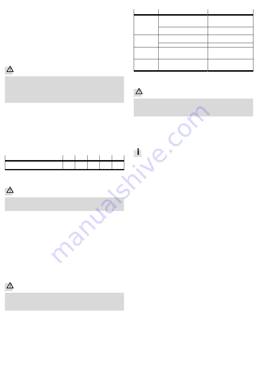
Connection size
[”]
1
1¼
1½
2
2½
Max. tightening torque
pipe connection
[Nm]
350
450
540
620
750
Fig. 7
9
Commissioning
Warning
Risk of injury from manipulation in the area of the angle seat valve!
Limbs can be cut or severed.
Place only the fully mounted angle seat valve in operation.
Prerequisites
– The valve is fully mounted and connected
Checking operating conditions
Observe operating conditions and limits
è
Technical data and product labelling.
Check connection points for tightness.
Check compatibility of the devices in the system for maximum pressure
(consider pressure peaks). If necessary, adjust the application parameters.
Placing valve in operation
1. Supply medium.
2. Slowly apply operating pressure to the valve. The operating pressure required
for reliable switching of the valve depends on the medium pressure
è
3. Function and direction control of the individual pneumatic actuators.
10
Operation
Danger
Risk of injury from touching hot surfaces!
Valve and actuator can become hot at high temperature of medium. Severe
burns are possible.
Do not touch the angle seat valve during operation or immediately afterward.
Comply with operating conditions.
Comply with maintenance conditions
è
Chap. 12.
After longer idle times:
Actuate the valve several times and check for correct function.
11
Malfunctions
Malfunction
Possible cause
Remedy
Valve does not
close or closes
too slowly
VZXA-B: medium pressure is too high
or operating pressure too low
Creating necessary differential
pressure
è
Adjust operating pressure.
Too many contaminants, or contamin
ants that are too large, in the medium
Comply with operating condi
tions.
Valve does not
open or opens
too slowly
VZXA-A: operating pressure is too low
or medium pressure too high
Adjust operating pressure or
medium pressure.
VZXA-B: operating pressure too low
Adjust operating pressure.
Medium leaking
from a leakage
hole
Seal cartridge defective
Replace seal cartridge
è
Spare parts documentation.
Medium will not
let itself be
shut off
Seat seal defective
Replace seat seal
è
Spare parts documentation.
Fig. 8
12
Maintenance
Danger
Risk of injury from touching hot surfaces!
Valve and actuator can become hot at high temperature of medium. Severe
burns are possible.
Allow the angle seat valve to cool off before working on it.
Check product regularly from the outside for leakage.
Check function of the product regularly.
Clean product regularly with commercial cleaners.
12.1 Proof Test
The proof test consists of turning the operating pressure off and back on.
Perform the proof test annually.
During the proof test, the safety of the application must be ensured.
1. Switch off the operating pressure.
2. Check valve position.
è
The test is successful if the safe status is reached within the specified time.
For evaluation of the safe status
è
3. Slowly apply operating pressure to the valve.
è
The test is successful if the valve takes its original position again.
4. Check the valve externally (visual inspection).
è
The test is successful if no defect or leakage is detected.
5. Document test results.


