6
Display and connecting elements of the valves
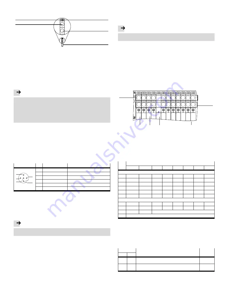
The subsequent figure shows the assignment of the LEDs to the solenoid coils of
the valves:
1
2
3
4
5
1
LED for solenoid coil 12
2
LED for solenoid coil 14
3
Manual override (MO) non-detent-
ing/detenting, solenoid coil 14
4
Manual override (MO) non-detent-
ing/detenting, solenoid coil 12
5
Valve
Fig. 3
7
Earth terminal
Connect the VTUG-PT-L to the functional earth via the earth terminal (
4
in
Fig. 1). In this way, you will avoid malfunctions from electromagnetic interference.
8
Voltage supply
Note
• Use for the electrical power supply only PELV circuits in accordance with
IEC/EN 60204-1 (Protective Extra-Low Voltage, PELV).
• Observe also the general requirements for PELV circuits in accordance with
IEC/EN 60204-1.
• Use only voltage sources that ensure a reliable electric separation of operat-
ing voltage in accordance with IEC/EN 60204-1
• Always connect both circuits for operating and load voltage supply.
Through the use of PELV circuits, protection against electric shock (protection
against direct and indirect contact) is ensured in accordance with IEC/EN 60204-1.
9
I-port connection
The VTUG-PT-L can be connected as follows via the I-port connection:
– directly to the fieldbus by mounting a CTEU bus node on the VTUG-PT-L
– decentralised to an external I-port-compatible device through a connecting
cable.
– to a CPX terminal through a connecting cable and a CTEL master module
(
CTEL system description).
9.1 Pin allocation of the I-port/IO-Link cable
Connection
1)
Pin
Allocation
Function
3
4
5
2
1
1
24 V
EL/SEN
(PS)
Operating voltage supply
2
24 V
VAL/OUT
(PL)
Load voltage supply
3
0 V
EL/SEN
(PS)
Operating voltage supply
4
C/Q
Data communication
5
0 V
VAL/OUT
(PL)
Load voltage supply
Housing, FE
Functional earth
2)
1)
5-pin M12x1 plug, A-coded
2)
The connection to the functional earth must also be ensured via the earthing screw 1 of the valve ter-
minal (see chap. ).
Fig. 4
10
IO-Link mode
The VTUG-PT-L can also be operated as an IO-Link device. You can download the
IODD configuration file required for this at
www.festo.com.
Note
If an IO-Link Master is used, the load voltage must normally be made available
through a T-plug.
11
Inscription labels
The valves of the VTUG-... can be equipped with an inscription label holder (
as-
sembly instructions ASCF-H-L1) or with identification plate holders (
assembly
instructions ASLR-D). The I-port sub-base can be equipped with the identification
plate ASLR-C-E4.
12
Manual override (MO)
Actuation of the MO under the holders of the inscription label holder ASCF-H-L1 or
under the identification plate holders ASLR-D, is only possible in a non-detenting
manner.
The MO VAMC-L1-CD is not permissible in combination with the inscription label
holder ASCF-H-L1.
Note
Destruction of the MO
• Observe the permissible actuating force of max. 20 N.
13
Address assignment
With the VTUG-PT-L you can actuate up to 48 solenoid coils. The subsequent figure
shows as an example the address allocation of the VTUG-PT-L with 12 valve posi-
tions (VP):
–
1
assigned addresses of the solenoid coils 12
–
2
assigned addresses of the solenoid coils 14
– The address assignment is independent of whether blanking plates
3
or
valves
4
are used.
– Address assignment is in ascending order without gaps, from left to right.
– A valve position always occupies two addresses. The following assignment ap-
plies in this case:
low-order valve position (address) for solenoid coil 14
high-order valve position (address) for solenoid coil 12.
15
5
7
9
11 13
17 19 21 23
14
4
6
8
10 12
16 18 20 22
VP 12
VP 1
1
2
3
4
1
2
3
0
1
assigned addresses of the solen-
oid coils 12
2
assigned addresses of the solen-
oid coils 14
3
Blanking plate
4
Valves
Fig. 5
14
Assignment of the outputs and inputs
The subsequent table shows assignment of the outputs and inputs.
Byte Bit
0
1
2
3
4
5
6
7
Outputs:
0
SP 1
1)
Sp 2
Sp 3
Sp 4
Sp 5
Sp 6
Sp 7
Sp 8
1
Sp 9
Sp 10
Sp 11
Sp 12
Sp 13
Sp 14
Sp 15
Sp 16
2
Sp 17
Sp 18
Sp 19
Sp 20
Sp 21
Sp 22
Sp 23
Sp 24
3
Sp 25
Sp 26
Sp 27
Sp 28
Sp 29
Sp 30
Sp 31
Sp 32
4
Sp 33
Sp 34
Sp 35
Sp 36
Sp 37
Sp 38
Sp 39
Sp 40
5
Sp 41
Sp 42
Sp 43
Sp 44
Sp 45
Sp 46
Sp 47
Sp 48
Inputs (V+):
0
Sp 1
Sp 2
Sp 3
Sp 4
Sp 5
Sp 6
Sp 7
Sp 8
1
Sp 9
Sp 10
Sp 11
Sp 12
Sp 13
Sp 14
Sp 15
Sp 16
2
Sp 17…32
Sp 33…48
not used
3
not used
1)
Sp = solenoid coil
Fig. 6
15
Malfunction and error handling
Malfunctions and statuses from connected I-port devices are transmitted in the
form of event codes through the bus node to the Fieldbus Master and output there
and stored, if necessary. In the diagnostics case, a 2-byte-long event code is trans-
ferred to the I-port or IO-Link master.
Event code
Malfunction and error handling
Type
MSB
LSB
50 h
00h
Device errors. Switch device off and back on. If the error is still
present, the device is defective and needs to be replaced.
Error
51 h
12 h
Error in the load voltage supply
•
Check the load voltage supply
Warning
Fig. 7


