5.2
Function
The SFAH measures the flow rate (standard flow rate, mass flow rate) with the
help of a thermal procedure. Measurements are carried out using a micromechan-
ical sensor element with a downstream electronic evaluation unit. Connection to
higher-level systems is provided by 2 switching outputs, an analogue output
and/or an IO-Link® interface. The outputs can be configured as appropriate to the
application. The switching outputs can be configured to monitor a threshold
value, signal range or signal change. The outputs can be set as PNP or NPN and
normally open (NO) or normally closed (NC). Through the IO-Link® interface, pro-
cess values can be read out and parameters changed and transmitted to addition-
al devices. Through integration of the flow rate, a volume/load signal can be cal-
culated and output via a pulse output as well as a cumulated measurement value
through IO-Link®.
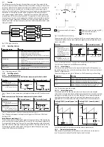
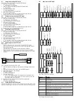
Fig. 2 SFAH signal structure
5.2.1
Operating statuses
Operating status
Function
RUN mode
–
Basic status after the operating voltage is applied
–
Display of the current measured value
–
Display of the selected inputs and outputs
–
Switchover between the measured variables of flow rate and
volume/mass
SHOW mode
–
Display of current settings of the switching outputs and ana-
logue output
–
Display and resetting of the minimum and maximum values
–
Display of the average flow rate measurement
EDIT mode
–
Setting of parameters
TEACH mode
–
Acceptance of the current measured value to determine
switching points
Tab. 3 Operating status of SFAH
5.2.2
Switching outputs
5.2.2.1
Switching functions
Threshold value comparator in the flow rate measurement for OutA or OutB
Function
NO (normally open)
NC (normally closed)
Switching function:
–
1 switching point (SP)
TEACH mode:
–
2 teach points (TP1, TP2)
Tab. 4 Threshold value comparator: setting of switching point [SP] and hysteresis
[HY]
Window comparator in the flow rate measurement for OutA or OutB
Function
NO (normally open)
NC (normally closed)
Switching function:
–
2 switching points (SP.Lo,
SP.Hi)
TEACH mode:
1)
–
2 teach points (TP1, TP2)
–
TP1 = SP.Lo, TP2 = SP.Hi
1) SP.Lo = smaller value, SP.Hi = larger value, independent of the teach sequence
Tab. 5 Window comparator: setting of switching points [SP.Lo] and [SP.Hi] and
hysteresis [HY]
Auto difference monitoring d_|¯|_
This function permits monitoring of a signal value for constancy. If the applied sig-
nal is constant in the range between [SP.Lo] and [SP.Hi], the reference signal qRef
is automatically determined. The result is a switching operation at the output and
signalises the start of the signal monitoring procedure. If the signal remains in the
monitoring range [d.SP] around qRef, the signal is stable. When the monitoring
range is left, the output switches back.
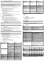
1 Reference value qRef is determ-
ined
2 Measured value deviates by [d.SP]
from the reference value
3 Monitoring range
Fig. 3 Auto difference monitoring
The parameters [SP.Lo], [SP.Hi], [t.obS] and [d.SP] can be configured by the user.
The greater [t.obS] is set, the more stable the signal must be to establish the ref-
erence value qRef.
Function
NO (normally open)
NC (normally closed)
Switching function:
–
2 switching points (SP.Lo,
SP.Hi) for setting the valid
work range
–
1 switching point (d.SP)
for determination of the
monitoring area
TEACH mode:
1)
–
2 teach points (TP1, TP2)
–
TP1 = SP.Lo, TP2 = SP.Hi
1) SP.Lo = smaller signal value, SP.Hi = larger signal value, independent of the teach sequence
Tab. 6 Window comparator: auto difference monitoring
5.2.2.2
Colour change
A red colour change can be set in the display for OutA and OutB, dependent on
the switching status. As a result, the switching status of the sensor can be identi-
fied over a large distance.
The colour change reacts both on OutA and on OutB, depending on the setting.
Parameter
Meaning
bLUE
Display is always blue; the colour change function is switched off.
R.On
Display is red when the switching output is set (high = 1).
Display is blue when the switching output is not set (low = 0).
R.OFF
Display is red when the switching output is not set (low = 0).
Display is blue when the switching output is set (high = 1).
Tab. 7 Colour change on the display
5.2.2.3
Volume/load pulse
A threshold value SP for the volume or load can be set in the accumulated
volume/load measurement. If the configured threshold value is reached, a switch-
ing impulse is emitted at the “Puls” output (
è
Fig.2) for an adjustable period of
time. With each switching impulse, the volume/load measurement is started
again (
è
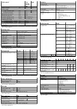
Tab. 8 Volume/load pulse with accumulated volume measurement).
Setting NO (N/O (normally open) con
tact)
Setting NC (N/C (normally closed)
contact)
Tab. 8 Volume/load pulse with accumulated volume measurement
5.2.3
Zero point synchronisation
With zero point synchronisation (Zero Adjust), the offset error can be reset to
zero. This synchronisation affects the display and all outputs.

