background image

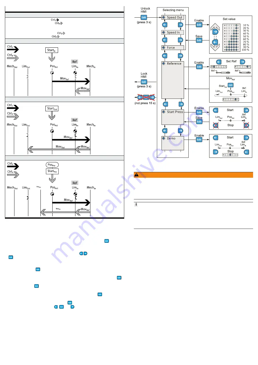
Homing after a restart as a function of the positioning task

Sequence

Mov

Ref

: force-controlled movement 

 against mechanical stop "Mech

In

"

Mov

Out

: position-controlled movement 

 to the reference end position "Ref"

Travel to the target position as a function of the positioning task

No travel, end position "Lim

In

" reached

Mov

Out

: position-controlled movement 

 to the end position Lim

Out

Mov

Imp

: position-controlled travel 

 to the intermediate position Lim

Imp

 (IO-Link only)

Start

In

 positioning task to the end position Lim

In

Start

Out

 positioning task to the end position Lim

Out

Start

Imp

 positioning task to the intermediate position Pos

Imp

 (IO-Link only)

Tab. 10: Initialise restart sequence with reference end position "Ref"

9.4

Display and operating components (HMI)

The display and operating components (HMI) can be used to perform the fol-
lowing functions in the HMI menu:

Unlock pushbutton actuators (Unlock HMI), press and hold for 3 s 

  — an

active positioning task in DIO or IO-Link mode is stopped
(Condition for IO-Link operation: IO-Link parameter 0x000C.4 = false)

Select menu function with pushbutton actuators     (selecting menu), press

Parameterise Speed Out, Speed In and Force setpoint values
(Set value: 10, 20, ..., 100% of the maximum value 

è

 14 Technical data) and

save (Save), press 

Parameterise the position of the reference end position "Ref" (Set Ref) and run
the referencing movement Mov

Ref

 (Start

Ref

: Pos

Act


è

 Lim

In


è

 Lim

Out

), press 

Run Start Press movement (Start/Stop) and save Start Press Position Pos

Start

Press

 (Save), press 

Execute demo run (Start/Stop)

Lock pushbutton actuators (Lock HMI), press and hold for 3 s 

 or no push-

button actuator input for 15 s

To acknowledge an error, press and hold 

 for 3 s

Reset to factory settings, press  , 

 and   simultaneously for 10 s and then

carry out a Power OFF/ON on the logic power supply 24 V DC [pin 1].

Fig. 8: HMI menu

9.5

Homing with end position determination

WARNING

Risk of injury due to unexpected movement of components.
When starting the homing run, the drive is disconnected from the power supply
for a short time. This can cause unexpected movements of the connected
mechanics and crush parts of the body.
• Bring moving parts of the connected mechanical system into a safe position.

• Referencing with end position determination is only required again if the refer-

ence end position "Ref" or the useful range needs to be changed.

• During referencing with end position determination the intermediate position

Pos

Imp

 and the start press position Pos

Start Press

 is set equal to the new end

position Lim

Out

.

During referencing with end position determination the positions of the mechan-
ical stops Mech

In

/Mech

Out

 are recorded in order to calculate the end positions

Lim

In

 ("Ref")/Lim

Out

 for the dimension reference system.

Before running referencing with end position determination to a new reference
end position "Ref", the drive is de-energised for a required re-initialisation. Then
the power is restored and the process is started.

Summary of Contents for EPCE-TB

Page 1: ...es and spare parts è www festo com catalogue 4 Product overview 4 1 Scope of delivery The following components are included in the scope of delivery Electric cylinder unit EPCE TB Instruction manual for the electric cylinder unit EPCE TB Adapter for IO Link operation optional accessory è www festo com catalogue 4 2 Function The electric cylinder unit converts the rotary motion of the mounted motor...

Page 2: ...ton rod may only be used for a short time during mounting è Tab 6 Information on attachment components Collision free Torque free Centre of gravity and tilting moment Tab 4 Requirement for attachment component Requirement No collision in the range of motion of the attachment component with mounting components No transverse load or torque on the piston rod Absorb external forces and torques via an ...

Page 3: ...e YE yellow 8 Commissioning WARNING Risk of injury due to unexpected movement of components Protect the positioning range from unwanted intervention Keep foreign objects out of the positioning range Perform commissioning with low dynamic response WARNING Severe irreversible injuries from accidental movements of the connected actuator technology Unintentional movements of the connected actuator tec...

Page 4: ...point to point operation with press function 0x0102 0 Force Force 0x0105 0 start press position PosStart Press reference point reference end position Ref Then the EMCS ST is ready for operation and the application can be controlled via the IO Link interface process data 0x0029 1 0x0029 2 and 0x0029 5 or system parameter 0x0002 è 9 6 Point to point operating modes 9 Operation WARNING Danger of burn...

Page 5: ...tartRef PosAct è LimIn è LimOut press Run Start Press movement Start Stop and save Start Press Position PosStart Press Save press Execute demo run Start Stop Lock pushbutton actuators Lock HMI press and hold for 3 s or no push button actuator input for 15 s To acknowledge an error press and hold for 3 s Reset to factory settings press and simultaneously for 10 s and then carry out a Power OFF ON o...

Page 6: ...y Speed Out 0x0101 0 Speed Out1 Velocity Speed In 0x0100 0 Speed In1 Force Torque 0x0102 0 Force1 2 Start Press Position PosStart Press 0x0105 0 Position Start Press mm 2 3 4 End position LimOut 0x0106 0 end position Out mm 4 Intermediate position PosImp 0x0108 0 Intermediate Position mm 3 4 Control point to point operation via digital inputs Positioning task Control signals MovIn DI1 Logic Pin 5 ...

Page 7: ...ediate circuit 0x180 6 Remedy Check the load voltage supply Check power socket for contamination 0x0026 38 Undervoltage in load supply 24 V 0x180 2 Remedy Check the load voltage supply Check power socket for contamination 0x0027 39 Overvoltage load supply 24 V 0x180 1 Remedy Check the load voltage supply 0x0031 49 Temperature in device too low 0x400 0 Remedy Check ambient conditions 0x0033 51 Temp...

Page 8: ...nting position kg 5 10 vertical mounting position kg 2 5 5 Max feed force Fx sum of all piston rods 1 2 N 85 150 Max force on external stops during homing3 N 97 186 Max velocity4 m s 0 44 0 6 Velocity Speed Press 5 mm s 20 20 Max acceleration deceleration5 m s2 9 9 Duty cycle 100 30 50 C 2 per Kelvin Min stop end position distance6 mm 0 5 Repetition accuracy mm 0 05 Feed constant mm rev 32 32 Nomi...

Reviews: