9.2
Procedure
WARNING
Danger of crushing.
The gripper fingers could move unintentionally and crush body parts.
• Do not reach into the movement range.
The gripper is controlled (open/close) by commands from a higher-order con-
troller to the digital inputs (Pin 2 and Pin 4). In this case, the gripper is edge-trig-
gered and moves on detection of a rising edge. As soon as a high signal level
is detected, travel to the stop is executed. Please ensure that, once travel is
complete, the corresponding signal is reset again before transmitting a signal in
the opposite direction. Pause times of at least 10 ms must be observed between
cancelling the signal and the next command.
If a signal remains at the high signal level until the next travel, this can prevent
unintended travel being initiated in the event of a cable break.
For certain gripping situations, it may be necessary to send an additional gripping
signal (max. 3x in one direction).
Behaviour in emergency off
–
In the event of an emergency off, the gripper jaws stop moving.
–
When the gripper grips a component, the position and force achieved are
maintained by the self-locking function of the jaws.
–
If the gripper jaws are in motion at the time the current is switched off, the
gripping process is no longer fully completed. A force cannot or can only be
partially dynamically applied.
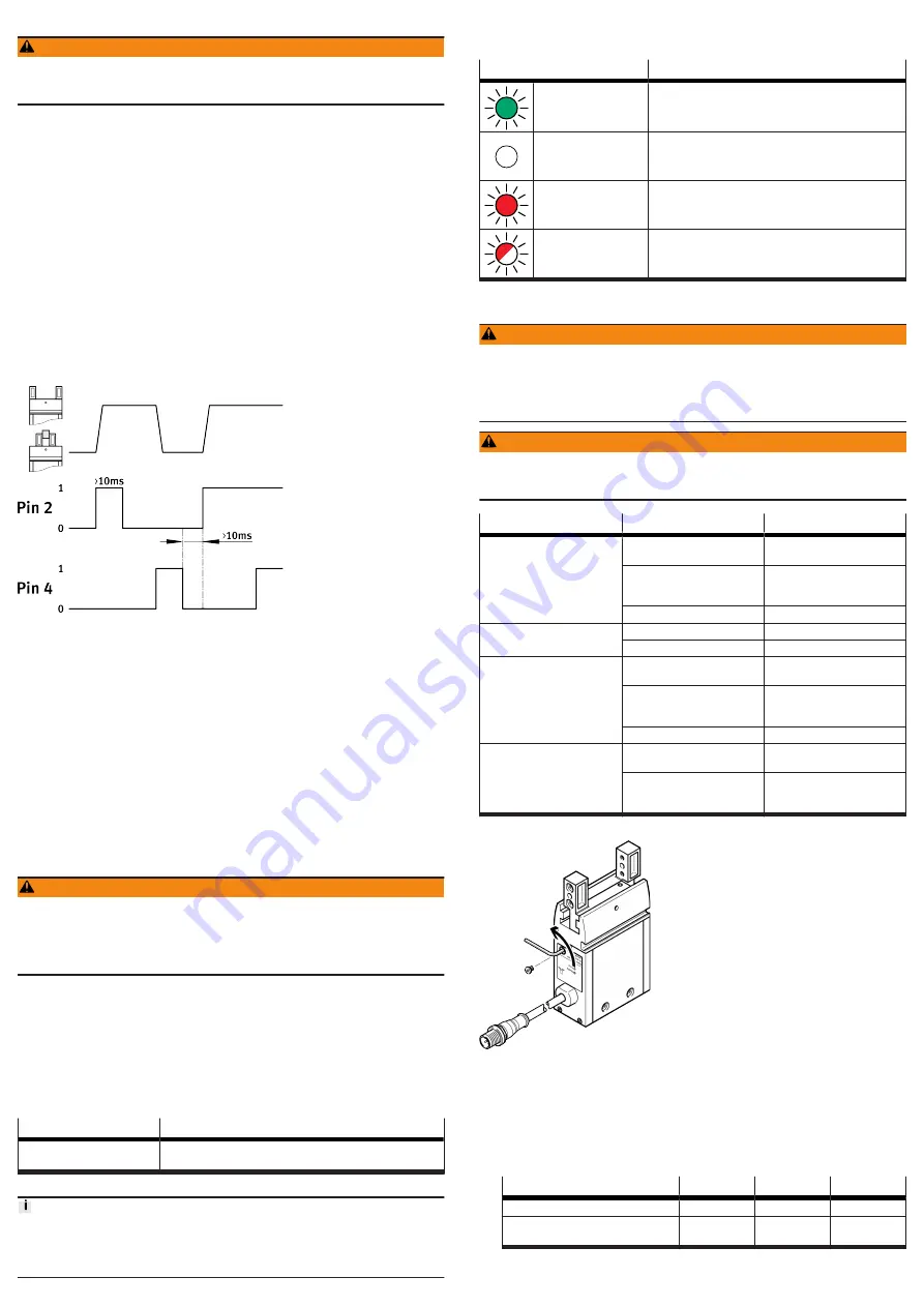
Fig. 7: Signal diagram
1. Switch on the power supply.
Ä
The Ready LED is green.
2. Open gripper jaws:
–
Apply a rising edge (0
è
1) at pin 2
–
Logic 0 at pin 4.
Pin allocation for connection
3. Approach the workpiece to be gripped.
4. Closing the gripper jaws:
–
Apply a rising edge (0
è
1) at pin 4
–
Logic 0 at pin 2.
5. Execute a test run. During the test, check that the workpiece is gripped
properly.
10
Maintenance
10.1
Safety
WARNING
Danger of crushing due to unexpectedly fast-moving loads and unintentional
movements.
• Remove the payload.
• Switch off power to the product.
• Safeguard the power supply from being switched on again unintentionally.
10.2
Cleaning
Clean the product with a soft cloth. Do not use aggressive cleaning agents.
For use with reduced particle emission:
–
Remove abrasion and contamination from the product on the following
schedule:
–
Prior to initial commissioning.
–
Regularly during operation.
10.3
Lubrication
Interval
Maintenance work
After 5 million switching cycles
Grease the guide of the gripper jaws. Permissible lubricating
grease
Tab. 4
Cut the lubrication interval by half if one of the following applies:
• High thermal stress
• Heavy contamination
• Proximity of grease-dissolving liquids or vapours
11
Malfunctions
11.1
Diagnostics
LED
Meaning
Ready LED is green
Nominal operating voltage at connection
3
pin 1 is
24 V DC ± 10%.
Ready LED is off
Nominal operating voltage is switched off.
Error LED is red
Nominal operating voltage at connection
3
Pin 1 is outside
the valid range.
Error LED flashes red
Device error
Tab. 5: LED
11.2
Fault clearance
WARNING
Danger of crushing due to unexpectedly fast-moving loads and unintentional
movements.
• Remove the payload.
• Switch off power to the product.
• Safeguard the power supply from being switched on again unintentionally.
WARNING
Danger of crushing.
The gripper fingers could move unintentionally and crush body parts.
• Do not reach into the movement range.
Fault description
Cause
Remedy
Gripper does not hold payload
securely.
Gripping point of gripper fin-
gers is too far outwards.
Move gripping point inwards.
Sufficient force cannot be
applied.
Increase travel path. Minimum
travel
Payload is too heavy.
Select a larger gripper.
Gripper fingers do not move
uniformly.
Slots are dirty.
Clean and grease the slots.
Gripper jaws are distorted.
Rectify distortion.
Gripper fingers do not open/
close.
Jamming due to excessive
speed of the gripper fingers.
Resolve jamming
Interruption of communication
between gripper and control
unit.
Check connecting cable.
Gripper is faulty.
Replace gripper.
Squeaking noises
Lack of lubrication
Lubricate gripper
Payload is too great.
Observe permissible values
Tab. 6: Fault clearance
Fig. 8: Resolve jamming of gripper jaws
1. Remove the plug screw.
2. Rotate the worm shaft underneath using the hex wrench until the jamming is
resolved:
–
Anti-clockwise (external gripping)
–
Clockwise (internal gripping)
3. Retighten plug screw.
EHPS
-16
-20
-25
Hex wrench
ß
1.5
ß
1.5
ß
2
Tightening torque for plug
screw
[Nm]
0.6
0.6
2.8


