

DNCE−...−LAS−...−C
Festo AG & Co. KG
Postfach
D−73726 Esslingen
++49/711/347−0
www.festo.com
(en) Operating instructions
745758
0906a
Original: de
Note
Fitting and commissioning is to be carried out only by qualified personnel in
accordance with the operating instructions.
1
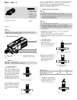
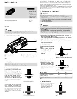
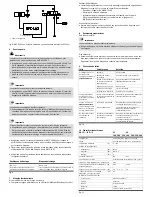
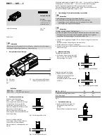
Operating elements and ports
1
2
3
1
Electric cylinder
2
Clamping unit
3
Compressed air connection
(released by transport screw)
Fig.1
Definition
DNCE−LAS
Electric cylinder
DNCE−LAS−C
Electric cylinder with clamping unit
2
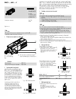
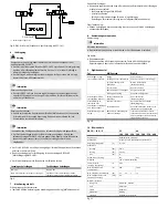
Function and application
The electric cylinder with
DNCE−...−LAS−...−C clamping unit holds
the piston rod with frictional locking in
an intermediate or end position of the
electric cylinder. When the supply port
3
is exhausted, a spring pushes the
clamping jaws apart. When the
clamping jaws are pushed apart, they
are tilted onto the piston rod. This
frictional locking holds the piston rod.
Fig.2: Piston rod clamped
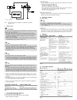
When the supply port
3
is pressurized,
a piston pushes the clamping jaws
together. The holes in the clamping
jaws are now aligned with the piston
rod. The piston rod can now move
freely.
Fig.3: Piston rod released
The electric cylinder with DNCE− LAS−, −C clamping unit attached is intended to hold
the piston rod of a DNCE−LAS electric cylinder (e.g. when installed vertically).
The piston rod must not be clamped when moving (= braking).
In the event of sudden pressure failure, the DNCE−LAS−C may only be used if
followed by a functional test (
è
Operation).
3
Conditions for the safe use of the product
Note
The clamping unit may be damaged if the piston rod is braked.
· Make sure that with cyclic clamping the following specifications are observed:
The clamping unit is pressurized and exhausted only when the clamping rod
has come to a complete standstill.
There are no dynamic forces present.
Note
Incorrect handling can lead to malfunctioning.
· The DNCE−LAS operating instructions must be observed at all times.
The technical specifications of the electric cylinder with DNCE−LAS−C clamping
unit may restrict the details in the operating instructions of the DNCE−LAS
electric cylinder.
· Slowly pressurize the complete system. This will prevent uncontrolled
movements from occurring.
For slow start−up pressurisation use soft−start valve type HEL.
· Use the product without any unauthorized modifications.
· Note the warnings and instructions on the product and in the relevant operating
instructions.
4
Mechanical assembly
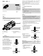
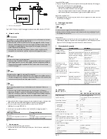
To unlock temporarily by hand:
· Using a round bar
4
(e.g. Ø 4 x 50 mm), press the piston
against the spring force until the
piston rod can be moved freely.
4
Fig.4: Releasing the clamp (briefly)
For permanent unlocking when setting:
· Screw an M5 screw 5 into the
threaded hole on the compressed air
port until the piston rod can be
moved freely. Max. permissible
torque is 0.5 Nm.
Fig.5: Releasing the clamp
(permanently)
DNCE−...−LAS−...−C
32
40
Compressed air port/screw size
M5
G
Á
Min. screw length
[mm]
16
22
Fig.6
5
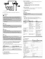
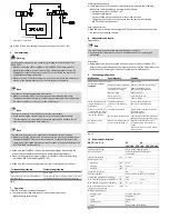
Installing the pneumatic system
· Connect the compressed air supply
3
The tightening torque is 0.5Nm.
A control example is given below.
Fig.7


