11.3 LED indicators
Various LED indicators are available on every module for the visualisation of the
statuses and errors. In the process, LED indicators specific to the system and
module or network are differentiated.
The system-specific LED indicators of the controllers and bus modules are
described in this document.
LED indicators specific to the module or network are described in the
documentation for the respective module.
Power System [PS] – Operating voltage supply U
EL/SEN
LED (green)
Significance
Remedy
Lights up
ON
OFF
Voltage supply present.
No error.
–
Flashes
ON
OFF
Voltage supply present, but
outside of the tolerance
range.
Eliminate undervoltage.
The link on the bus module
is missing or incomplete.
Check the link.
Flashes
ON
OFF
The internal fuse of the
voltage supply has
responded.
Eliminate short circuit/overload.
Depending on the parameterisa
tion, the voltage supply is then
switched on automatically again
(factory setting) or it must be
switched off and then on again.
Off
ON
OFF
Voltage supply not present.
Check connection of the power
supply.
Fig. 15
Power Load [PL] – Load voltage supply U
OUT
LED (green)
Significance
Remedy
Lights up
ON
OFF
Voltage supply present.
No error.
–
Flashes
ON
OFF
Voltage supply present, but
outside of the tolerance
range.
Eliminate undervoltage.
Off
ON
OFF
Voltage supply not present.
Check connection of the power
supply.
Fig. 16
System Failure [SF] – System failure
LED (red)
1)
Significance
Remedy
Flashes
ON
OFF
Simple error/information
(error class 1)
è
Description of the CPX-E system
ON
OFF
Error
(Error class 2)
ON
OFF
Serious error
(Error class 3)
Off
ON
OFF
No error
–
1)
The LED indicator “System Failure” [SF] flashes depending on the error class.
Fig. 17
Modify [M] – Parameterisation modified or “Force” active.
LED (yellow)
Significance
Lights up
ON
OFF
System start with saved parameterisation and saved CPX
expansion set; parameters and CPX expansion are saved
remanently; external parameterisation is blocked
1)
Caution when replacing systems with saved parameterisation. In
the case of these systems, parameterisation is not carried out
automatically by the higher-order controller on replacement.
Before replacement, note required settings and restore them
after replacement, if required.
Flashes
ON
OFF
The Forcen function is enabled.
1)
Off
ON
OFF
System start with default parameterisation (factory setting) and
current CPX expansion set; external parameterisation is possible
(presetting).
1)
The indication of the “Forcen” function (LED flashing) has priority over indication of the setting for the
system start with the saved parameterisation and saved extension (LED lights up).
Fig. 18
12
Maintenance
Note
Accumulation of heat due to reduced air supply to electronics.
Keep the ventilation slots free and regularly remove contamination.
13
Conversion
13.1 Replacing the module
Note
When a bus module, controller or complete system is replaced, a different
parameterisation will result in deviating behaviour.
Before replacement, check which settings are required and restore them after
the replacement.
Removing the terminal strips
If a module is exchanged within the course of a conversion or repair, the conductor
remains in the terminal strip and the terminal strips are removed from the module.
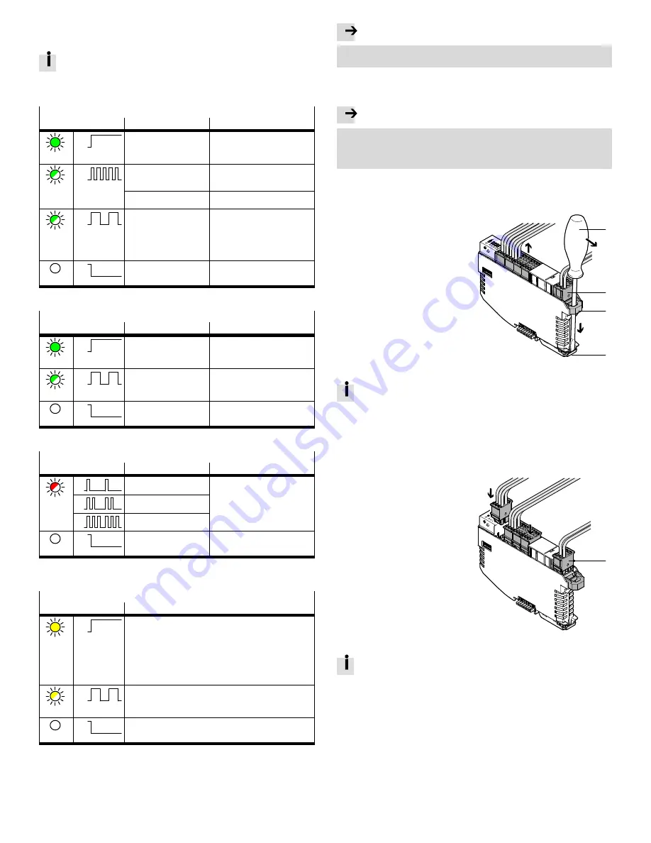
1. Ensure that the module is
de-energised.
2. Insert the screwdriver through the
recess of the terminal strip interlock
and into the module interlock.
3. Pull the screwdriver in the direction
of the arrow to disengage the
terminal strips.
4. Remove the terminal strips.
1
2
3
4
2.
3.
4.
1
Screwdriver
2
Terminal strip
3
Interlock of terminal strips
4
Interlock of module
Fig. 19
After the terminal is disengaged, it remains in a stopped position. The ter
minal strips that are not removed must be pushed back in to the limit stop.
Disengaging and removing the module
è
Fig. 11
Hanging the module into place and engaging it
è
Fig. 10
Inserting terminal strips
1. Ensure that the module is
de-energised.
2. Place the terminal strips in the
appropriate positions on the module.
3. Press in the terminal strips to the
limit stop.
1
2.
3.
1
Terminal strip
Fig. 20
To prevent connection faults, the terminal strips of the signals and terminal
strips of the voltage supply have matching codes.


