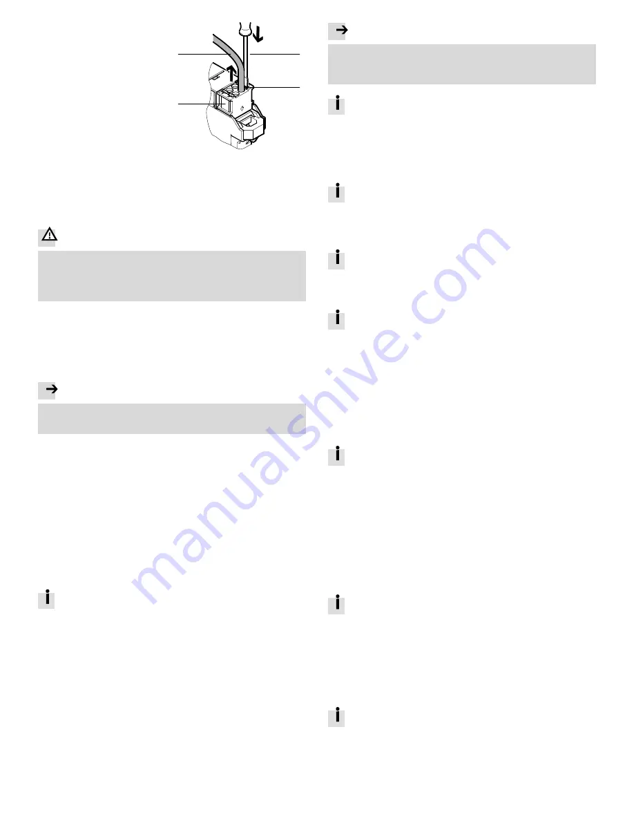
8.3 Disconnecting cables
1. Make sure the module and line are
de-energised.
2. Disengage the spring-loaded ter
minal interlock (e.g., with a slotted
screwdriver).
3. Pull the line from the terminal strip.
1
2
3
4
2.
3.
1
Slotted head screwdriver
2
Interlock of spring-loaded terminal
3
Terminal strip
4
Cable
Fig. 14
9
Commissioning
The behaviour of the CPX-E system during commissioning is largely determined by
the parameterisation of the bus module.
Observe information on parameterisation in the description of the bus node
è
1.1 Further applicable documents.
Warning
Risk of injury due to uncontrolled movements of the connected actuators.
The CPX-E system starts even if the parameterisation process is incomplete.
Keep the range of movement of the connected actuators unobstructed.
Check the parameterisation and address allocation of the inputs and/or
outputs (e.g., using Force mode).
In order to avoid connecting and addressing errors, you must carry out the
commissioning steps as follows.
1. Check the mounting and electrical connections
è
9.1.
2. Make settings on the bus module or controller
è
9.2.
3. Functional test (without higher-order controller)
è
9.3.
4. Commissioning in network (with higher-order controller)
è
9.4.
5. Parameterisation
è
9.5.
Note
Addressing errors caused by changing address ranges during operation.
Do not connect the bus module/controller to the network until after the func
tional test (
è
9.3).
9.1 Checking the mounting and electrical connections
1. Check the mounting of the CPX-E system.
Make sure the linking elements are clipped onto the H-rail and engaged in
each other.
Make sure all module interlocks are engaged to the H-rail.
Make sure all terminal strip interlocks are engaged to the H-rail.
2. Check the electrical installation of the CPX-E system.
Check the connections of the functional earth.
Check the connected lines for a firm seat.
Check the feed of the voltage supplies.
Check the allocation of the sensors and actuators to the modules.
9.2 Make settings on the bus module or controller
Settings are made on the bus module or controller independently of the module
using rotary and/or DIL switches.
The functions and factor settings of the rotary and DIL switches (if existent
on the module) are described in the respective documentation
accompanying the product.
Make the desired settings on the bus module or controller if they deviate from
the factory setting.
9.3 Functional test (without higher-order controller)
1. Switch on the power supplies (U
EL/SEN
, U
OUT
).
2. Check the behaviour of the CPX-E system:
– LED displays
– Connected actuators
9.4 Commissioning in network (with higher-order controller)
Note
Malfunction due to the activation of the higher-order controller and CPX-E
system in the incorrect order.
Switch on the higher-order controller and CPX-E system according to the pre
set order of the network used.
Information on commissioning can be found in the “Instructions for use”
for the respective bus module
è
1.1 Further applicable documents.
9.5 Parameterisation
With the aid of parameterisation, the behaviour of the CPX-E system the
individual modules and channels can be adapted to each particular application.
Parameterisation can be performed using suitable software from Festo or using
the higher-order controller. The parameters are preset at the factory.
The possibilities of parameterisation depend on the bus module or
controller used (
è
Description of the respective bus module/controller).
A list and description of the general parameters can be found in the
“Description of the CPX-E system”
è
1.1 Further applicable documents.
Parameterisation using Festo software
Suitable software for parameterisation can be found on the support portal
of Festo
è
www.festo.com/sp. Information for the use of the software is
included in the integrated help function.
Parameterisation using the higher-order controller
Information on parameterisation using the higher-order controller can be
found in the description of the respective bus module or controller.
Start-up behaviour of the CPX-E system
The “System start” system parameter fundamentally influences the start-up
behaviour of the CPX-E system.
– “Standard parameters” setting (presetting):
The CPX-E system starts with the factory setting.
The desired parameterisation can be established by the higher-order controller.
– “Stored parameters” setting
The CPX-E system starts with the parameters saved in the bus module.
The setting is signaled by the lighting of the “Modify” LED indicator [M]
è
5.3 Display components.
If the “Modify” LED indicator [M] is lit continuously, the parameterization of
the system is not restored automatically by the higher-level controller
after a replacement.
Before replacement, note the required parameters and re-establish
them again after replacement.
10
Operation
The behaviour of the system in case of an error with the following malfunctions is
dependent on the parameterisation of the higher-order controller and the setting
of the system parameters “Fail safe”:
– Telegram failure
– Network interruption
Depending on the parameterisation, the electrical outputs are switched off
(factory setting), switched on or retain their status.
Detailed information on the “Fail safe” can be found in the “Description of
the CPX-E system”
è
1.1 Further applicable documents.
11
Diagnostics and fault clearance
11.1 Diagnostics options
For the diagnosis of errors, various possibilities are available depending on the
parameterisation and network protocol used:
– Internal system diagnosis
– LED indicators on the product
11.2 Internal system diagnosis
The internal system diagnosis is described in the “Description of the CPX-E
system” and the module descriptions
è
1.1 Further applicable documents.


