2.2
Intended Use
The product described in this document is intended only for use as an interface
between an Automation system CPX-E and a higher-order controller through
integration in an PROFINET IO network.
Use the product only as follows:
–
Use only in an industrial environment. Outside industrial environments,
e.g. in commercial and residential/mixed-use areas, it may be necessary to
take measures to suppress radio interference.
–
Use only in combination with modules and components that are permissible
for the respective product variant
è
–
Only use the product if it is in perfect technical condition.
–
Only use the product in original status without unauthorised modifications.
Only the conversions or modifications described in this and the further applic-
able documents are permitted.
2.3
Training of Qualified Personnel
Installation, commissioning, maintenance and disassembly should only be con-
ducted by qualified personnel. The qualified personnel must be familiar with
installation of electrical control systems.
3
Further information
–
Accessories
è
–
Spare parts
è
4
Service
Contact your regional Festo contact person if you have technical questions
è
5
Product overview
5.1
Function
The product acts as a participant in a PROFINET IO network, establishing a con-
nection between a higher-order controller and the modules in an
automation system CPX-E.
Web server
The integrated web server provides read access to the key parameters and dia-
gnostic functions of the automation system CPX-E. The web server can be
accessed by entering the IP address in the address bar of a web browser.
Factory settings of the bus module:
IP address: 192.168.10.3, subnet mask: 255.255.255.0
5.2
Configuration
5.2.1
Product Design
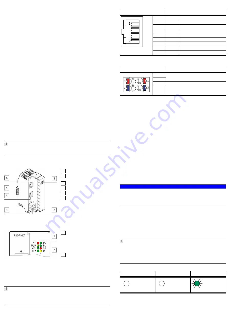
1 LED displays
2 Terminal strip for operating
voltage supply U
EL/SEN
[XD]
3 Terminal strip interlock
4 Network connection [XF2]
5 Linking element
6 Network connection [XF1]
Fig. 1
5.2.2
Display Components
1 Network-specific LED displays:
– Network fault [NF] (red)
– Maintenance [M/P] (yel-
low/green)
– Connection/data traffic
[XF1]/[XF2] (green)
2 System-specific LED displays:
– Operating voltage supply
U
EL/SEN
[PS] (green)
– Load voltage supply U
OUT
[PL]
(green)
– System error [SF] (red)
– Force mode [M] (yellow)
Fig. 2 LED displays
The network-specific LED displays are described below
è
The system-specific LED displays are described in the documents for the automa-
tion system CPX-E
è
5.2.3
Connecting Elements
Connection [XF1], [XF2]
Signal
1
TD+
Transmitted data +
2
TD–
Transmitted data –
3
RD+
Received data +
4
n.c.
–
5
n.c.
–
6
RD–
Received data –
7
n.c.
–
8
n.c.
–
1)
Shield
Functional earth
1) Housing
Tab. 5 Connection [XF1], [XF2]
Port [XD]
1)
Signal
0
1
+24 V DC operating voltage supply U
EL/SEN
2
3
0 V DC operating voltage supply U
EL/SEN
1) The ports XD.0 and XD.1 and also XD.2 and XD.3, respectively, are interconnected in the terminal strip.
Tab. 6 Port [XD]
6
Transport and storage
•
Observe specifications for environmental and storage conditions
è
Tab. 15 Ambient Conditions UL/CSA.
7
Assembly
•
Assemble the module as outlined in the “Instruction manual for Automation
system CPX-E”
è
8
Installation
8.1
Network
•
Use cables as described in the cable specification
è
Tab. 15 Ambient Conditions UL/CSA.
8.2
Operating Power Supply U
EL/SEN
1. Please note the information in the “Instruction manual for Automation system
CPX-E”
è
2. Make sure that the power supply is switched off.
3. Connect the lines to the terminal strip in accordance with the “Instruction
manual for Automation system CPX-E”
è
9
Commissioning
NOTICE!
Malfunction due to switching on the higher-order controller and automation
system CPX-E in the incorrect order.
•
Switch on the higher-order controller and automation system CPX-E according
to the preset order of the network used.
1. Using the appropriate software, set up an automation project for the higher-
order controller.
2. Import the device description file into the software
è
3. Automation system CPX-E Configure in the software:
–
System structure
–
Network addressing
–
I/O addressing
4. Transfer the automation project to the higher-order controller.
You can find information on commissioning the automation system CPX-E in the
“Instruction manual for automation system CPX-E”.
Information on the parameters can be found in the "Description of the
automation system CPX-E" and in the descriptions of the modules used
è
9.1
Behaviour of the Display Components after Error-free Commissioning
[NF] (red)
[M/P] (yellow/green)
[XF1], [XF2] (green)
Off
Off
Lights up
Tab. 7 Display Components after Error-free Commissioning


