4.1 Operating voltage supply X1 (V-El.)
Pin
Designation/
signal
Explanation
X1.1
24
Operating voltage supply (+24 V DC)
X1.2
0
Operating voltage supply (load)
X1.3
Functional earth
X1.4
–
Not connected
Fig. 11 Operating voltage supply X1
Besides the power supply of the controller, the power supply of the following in
terfaces also flows through this connection:
– Fieldbus interface
X6
– USB interface
X7
– Ethernet interface
X8
– Serial interface modules
X12 and X13 (CECC-S)
– Multiple interface
X14 (CECC-S)
– IO-Link Device Port
X16 (CECC-LK and CECC-S)
– Encoder interface
X11 (CECC-S)
è
Section 4.4
The operating voltage supply for the I/O interfaces and the load voltage supply for
the IO-Link Master Port are fed in separately.
4.2 Infeed of operating voltage supply X5 for the I/O interfaces
Pin
Designation/
signal
Explanation
X5.1
24
Infeed of operating voltage supply (+24 V DC)
for the I/O interfaces X2
…
X4 (digital input, digital output)
X5.2
0
Infeed of operating voltage supply (load)
for the I/O interfaces X2
…
X4 (digital input, digital output)
Fig. 12 Operating voltage supply X5 for the I/O interfaces
4.3 Infeed of load voltage supply X11 for IO-Link Master Ports
This connection is used for infeeding the load voltage supply of IOLink Devices,
which are connected via IOLink-Master Ports.
Connection to CECC-LK (V-IOL)
Pin
Designation/
signal
Explanation
X11.1
24
Infeed of load voltage supply (+24 V DC)
for IO-Link Master Ports X12.4
…
X15.4.
X11.2
X11.3
0
Infeed of load voltage supply (load)
for IO-Link Master Ports X12.5
…
X15.5.
X11.4
Fig. 13 Infeed of load voltage supply X11 at the CECC-LK
Connection to CECC-S (24 V DC/UE)
Note
Damage to the controller from mixing up the connection pins.
Use only the connecting pins X11.1 and X11.2 for infeed of the load voltage
supply of the IO-Link Master Ports at the CECC-S.
Pin
Designation/
signal
Explanation
X11.1
24
Infeed of load voltage supply (+24 V DC)
for IO-Link Master Port X15.4.
X11.2
0
Infeed of load voltage supply (load)
for IO-Link Master Port X15.5.
Fig. 14 Infeed of load voltage supply X11 at the CECC-S
4.4 Operating voltage supply X11 for encoders
Connection to CECC-S (24 V DC/UE)
Note
Damage to the controller from mixing up the connection pins.
Use only the connecting pins X11.3 and X11.4 for the load voltage supply
of the encoder at the CECC-S.
Pin
Designation/
signal
Explanation
X11.3
UG
Operating voltage supply (GND) for encoder X14
X11.4
UE
Operating voltage supply (5 V) for encoder X14
Fig. 15 Operating voltage supply X11 for encoders
Note
Malfunction due to undefined switching statuses of the electronics.
Use USB storage medium and encoder whose total current consumption
is maximum 0.5 A
è
Section 3.3.
5
Mounting, dismounting
Prior to mounting, installation and maintenance work:
Switch off power supply and secure it from being switched back on.
Mount the controller on an H-rail (
è
5.1) or on the wall (
è
5.2).
Note
Malfunction due to heat accumulation.
Mount the controller with sufficient space for heat dissipation.
Comply with limits of the ambient temperature ranges
è
Section 8.
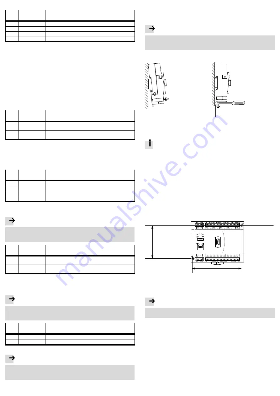
5.1 H-rail mounting
1
1
Spring-loaded clip
Fig. 16 Mounting/dismounting with H-rail mounting
Assembly
The tilt position of the CECC when setting it onto the H-rail requires
a minimum distance between the H-rail edge and the mounting surface
so the CECC can be placed onto the H-rail without tilting.
Use H-rail with a minimum depth of 9 mm.
1. Place controller onto the H-rail from above.
2. Press the controller in the direction of the arrow.
The spring-loaded clip engages audibly on the H-rail.
Disassembly
1. Remove connections from the controller.
2. Pull the spring-loaded clip of the controller in the direction of the arrow using
a suitable tool (e.g. screwdriver). This unlocks the controller.
3. Tilt the unlocked controller from the bottom away from the H-rail.
4. Lift controller upward from the H-rail.
5.2 Wall mounting
1
1
81
122.2
1
Mounting holes
Fig. 17 Mounting holes for wall mounting
Assembly
Note
Damage to the controller from mounting onto uneven or flexible surfaces.
Mount the controller only on even, torsionally rigid surfaces.
1. Plan sufficient space for connecting the supply cables.
2. Drill holes into the mounting surface. Note the distances between the mounting
holes.
3. Fasten the controller with screws:
Make sure that the housing is not damaged.
Use M4 screws of appropriate length and a screw head diameter of maximum
7.0
mm. Tightening torque: 0.8
Nm ± 20
%.
Dismounting
1. Remove connections from the controller.
2. Remove the mounting screws.
3. Remove the controller from the mounting surface.


