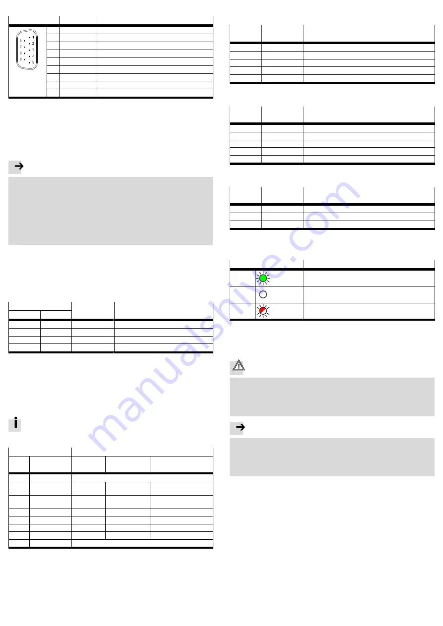
3.2 Fieldbus interface X6
Pin
Signal
Explanation
1
N.c.
Not connected
2
CANBus signal (dominant low)
3
CAN_GND
CAN Ground
4
N.c.
Not connected
5
CAN_SHLD
Functional earth
6
CAN_GND
CAN Ground (optional)
7
CAN_H
CANBus signal (dominant high)
8
N.c.
Not connected
9
N.c.
Not connected
1)
If the controller is at the end of the cable:
Connect pin 2 and pin 7 using a terminating resistor (120 ohms/0.25 W).
Appropriate CAN bus plugs (adapters) from Festo
è
www.festo.com/catalogue
Fig. 4
Fieldbus interface X6
3.3 USB interface X7
The USB interface enables external storage media to be connected using USB plug
type A.
Note
Malfunction due to undefined switching statuses of the electronics.
If a USB hard disk without its own power supply is used, the maximum permitted
current consumption can be exceeded, e.g. when the USB hard disk is running up.
Controller CECC-D and CECC-LK:
Use only storage media with current consumption
100 mA.
Controller CECC-S:
USB storage medium and encoder are supplied from a common power source.
Use USB storage medium and encoder whose total current consumption
500mA.
3.4 Ethernet interface X8
The Ethernet interface
1
è
Fig. 2 enables connection of a programming unit, PC
or operator unit to the controller.
The Ethernet interface is designed as an RJ45 socket.
3.5 Serial interfaces X12 and X13 (CECC-S)
Pin
Designation/
signal
Explanation
RS232-1
RS232-2
X12.1
X13.1
G
Data reference potential
X12.2
X13.2
TX
Transmitted data
X12.3
X13.3
RX
Received data
X12.4
X13.4
S
Shield, functional earth
Fig. 5
Serial interface modules X12 and X13
3.6 Multiple interface X14 (CECC-S)
The controller CECC-S has a combined interface with the following connection
options:
– Encoder (ENC, RS422-based encoders only)
– RS422
– RS485
Simultaneous use of these connection options is not possible.
Configure and use only one of the three connection options with
CODESYS.
Connection option
Explanation
Pin
Designation/
signal
Encoder
RS422
RS485
X14.1
G
Load
X14.2
A+
Track A+
Transmitted
data+
Transmitted/received
data+
X14.3
A–
Track A–
Transmitted
data-
Transmitted/received
data–
X14.4
B+
Track B+
N.c.
X14.5
B–
Track B–
Received data–
N.c.
X14.6
N+
Zero track+
N.c.
N.c.
X14.7
N–
Zero track–
N.c.
N.c.
X14.8
S
Shield, functional earth
1)
If the controller is at the end of the cable:
Connect pin X14.2 and pin X14.3 using a terminating resistor (120 ohms/0.25 W).
Connect pins X14.4 and X14.5 using a terminating resistor (120 ohms/0.25 W).
Fig. 6
Multiple interface X14
3.7 Communication interfaces IO-Link
4 x IO-Link Master Port X12…X15 (CECC-LK: IOL-M...)
Pin
Designation/
signal
Explanation
X12 … X15.1
L+
Operating voltage supply (24 V)
X12 … X15.2
C/Q
Data communication
X12 … X15.3
L–
Operating voltage supply (0 V)
X12 … X15.4
24
Load voltage supply (24 V) from X11
X12 … X15.5
0
Load voltage supply (0 V) from X11
Fig. 7
IO-Link Master Port X12…X15
1 x IO-Link Master Port X15 (CECC-S: IOL-M)
Pin
Designation/
signal
Explanation
X15.1
L+
Operating voltage supply (24 V)
X15.2
C/Q
Data communication
X15.3
L–
Operating voltage supply (0 V)
X15.4
24
Load voltage supply (24 V) from X11
X15.5
0
Load voltage supply (0 V) from X11
Fig. 8
IO-Link Master Port X15
1 x IO-Link Device Port X16 (CECC-LK and CECC-S: IOL-D)
Pin
Designation/
signal
Explanation
X16.1
L+
Operating voltage supply (24 V) from X1
X16.2
C/Q
Data communication
X16.3
L–
Operating voltage supply (0 V) from X1
Fig. 9
IO-Link Device Port X16
3.8 LED indicators
The following LED indicators signal the normal operating status of the controller:
LED
Meaning
Run
Lights up
green
Program running
Error
Off
No error
Net
Flashes
red
Controller has been identified in the network
Fig. 10 LED indicators
All LED indicators
è
4
Power supply
Caution
Risk of injury due to electric shock
For the electric power supply, use only PELV circuits that ensure a reliable
electric disconnection from the mains network.
IEC60204-1/EN60204-1 to be screwed in.
Always connect all circuits for operating and load voltage supply.
Note
The product may only be supplied from a single power source that fulfils the require
ments of energy-limited circuits in conformity with IEC/EN/UL/CSA 61010-1 or of
an energy-limited voltage source (limited power sourse, LPS) in conformity with
IEC/EN/UL/CSA60950-1 or IEC/EN/UL/CSA 62368-1 or of a class 2 circuit in con
formity with NEC or CEC.


