


CMMOST-...-DION/DIOP
28
Festo – GDPC-CMMOST-EA-S1-Z6 – 2017-05d – English
2.1
Circuitry of the control ports
To protect against unintended start-up, the motor controller must be activated via the
connector [X3] based on the category required for the application according to EN ISO
13849-1. Attainable safety level of the STO function
è
The following components can be connected to the control ports (
è
Tab. 8) to request the STO function:
– Semiconductor safety outputs (electronic safety switching devices, active safety sensors, e.g. light
curtains with OSSD signals) (OSSD = “Output Signal Switching Device”)
– Switch contacts (safety switching devices with relay outputs, passive safety sensors, e.g. forced
position switches)
3
4
5
1
2
+24 V DC, load
Festo CMMO-ST
3
4
Logic
Load
0 V
[X9]
2
3
ST
O1
ST
O2
[X3]
0 V DC
4
5
DIAG1
DIAG2
S1
OSSD1
OSSD2
S1
S1
S1
1
3
2
4
1
3
4
2
1
3
4
2
1
3
4
2
1
+24 V
+24 V DC, logic
2
1
5
Receiver
Transmitter
Input circuit
Fe
e
dba
ck
c
ir
cui
t
PL
C input:
Safety feedback
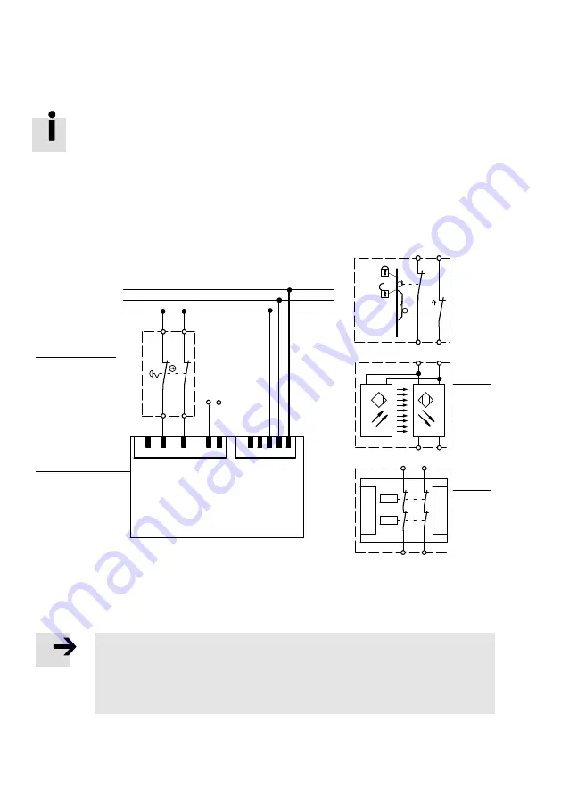
1
Motor controller with safety module
(only relevant connections shown)
2
Emergency stop switches
3
Guard door (alternative to
2
)
4
Light curtain (alternative to
2
)
5
Safety switching device (alternative to
2
)
Fig. 2
Switching example (without cross-circuit detection)
Note
The motor controller cannot detect a cross circuit in the input circuit by itself.
Determine if cross-circuit detection for the input circuit and the connection wiring is
required in your application.
If required, use a safety switching device with cross-circuit detection.


