background image

MEASURING

INSTRUMENTS

Page 2 of 10

Al

lr

ig

ht

s

ar

e

re

se

rv

ed

of

re

pr

od

uc

tio

n

an

d

di

ss

em

in

at

io

n

of

th

is

Te

ch

ni

ca

lM

an

ua

la

nd

do

cu

m

en

ta

tio

n

ci

te

d

an

d/

or

at

ta

ch

ed

.I

ti

s

ex

pr

es

sl

y

fo

rb

id

de

n

to

re

pr

od

uc

e,

pu

bl

is

h

or

di

st

rib

ut

e

an

y

in

fo

rm

at

io

n

fr

om

th

is

M

an

ua

l.

Co

py

rig

ht

by

FE

RV

I

FOREWORD

Read this manual before any operation

ORIGINAL INSTRUCTIONS

Before starting any operation it is compulsory to read this instruction manual. The guarantee

of smooth operation and full performance of the instrument is highly dependent on the
application of all the instructions contained in this manual.

Operator Qualification

The workers responsible for using this device must have all the necessary information,

education and receive adequate training regarding safety, including:
a)

The conditions of use of the equipment;

b)

Foreseeable abnormal situations, pursuant to Article 73 of Legislative Decree

81/08.

We guarantee the instrument complies with the specifications and technical
instructions described in the Manual on the date of its issuance (shown in this page).
On the other hand, the instrument may also be subject to important technical changes
in the future, without the manual being updated.
Therefore, see FERVI for information about modifications that could be implemented.

REV. 3

March 2014

fervi.com

Summary of Contents for T051

Page 1: ...USE AND MAINTENANCE MANUAL Pocket digital multimeter Art T051 ORIGINAL INSTRUCTIONS f e r v i c o m ...

Page 2: ...instructions contained in this manual Operator Qualification The workers responsible for using this device must have all the necessary information education and receive adequate training regarding safety including a The conditions of use of the equipment b Foreseeable abnormal situations pursuant to Article 73 of Legislative Decree 81 08 We guarantee the instrument complies with the specifications...

Page 3: ... 2 1 General Characteristics 5 2 2 Technical Specifications 5 2 2 1 Voltage DCV 5 2 2 2 Voltage ACV 6 2 2 3 Direct current DCA 6 2 2 4 Resistance 6 2 2 5 Audible continuity test and diode 6 3 USING THE MULTIMETER 7 3 1 Preliminary notes 7 3 2 Measurement of DC voltage DCV 7 3 3 Measuring direct current DCA 7 3 4 Measuring AC voltage ACV 7 3 5 Measuring resistors 8 3 6 Measuring diodes and continui...

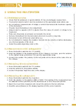
Page 4: ... tester is designed for measurements of AC voltage VAC DC voltage VDC direct current DC resistance diodes continuity Measuring voltage Always make sure that the switch is in the appropriate position To avoid electric shock use this instrument with caution Disconnect the circuit before starting the measurement Make sure that the AC voltage or DC voltage are not connected while measuring the resista...

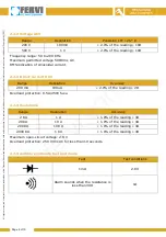
Page 5: ...ive polarity indication Number of measurements 2 3 times sec Low battery indication the battery symbol appears on the left side of the display Dimensions 120x70x20mm Weight 90 g including the batteries Batteries 12 V GP23A or equivalent 2 2 Technical Specifications Atmospheric conditions 0 40 C Relative humidity MAX 80 2 2 1 Voltage DCV Range Resolution Precision 18 2V 1 mV 0 8 of the reading 1D 2...

Page 6: ...e 50 to 200 KHz Maximum permitted voltage 500Vrms AC RMS indication of sinusoidal current 2 2 3 Direct current DCA Range Resolution Accuracy 200 mA 100uA 2 0 of the reading 2D Overload protection 0 5A 250V fuse 2 2 4 Resistance Range Resolution Accuracy 2 K 1 1 0 of the reading 4D 20 K 10 1 0 of the reading 4D 200 K 100 1 0 of the reading 4D 2000 K 1 K 1 0 of the reading 4D Maximum open circuit vo...

Page 7: ...ter use Do not attempt to measure the resistors inserted into live circuits or before discharging any internal capacity of the circuit Select the switch depending on AC or DC 3 2 Measurement of DC voltage DCV 1 Move the function switch to the V position 2 Point the selector to the desired position If the voltage is not know point the selector to the highest range and reduce it to reach the appropr...

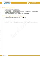
Page 8: ...ion 3 If the resistance to be measured is connected to a circuit turn off the power and deactivate it before applying the probes 4 Connect the probes to the resistor read the value on the display 3 6 Measuring diodes and continuity tests 1 Move the function switch to the position 2 Move the selector to the position with the diode symbol 3 Connect the red probe to the diode anode and the black prob...

Page 9: ... Opening the instrument Make sure that the instrument is disconnected and switched off before replacing the batteries 4 1 Battery replacement 1 When the batteries are almost used the battery symbol appears on the display 2 Turn off the appliance and disconnect the probes from the circuit before replacing the battery 3 Remove the cover on the back of the unit and replace the batteries making sure t...

Page 10: ...erved of reproduction and dissemination of this Technical Manual and documentation cited and or attached It is expressly forbidden to reproduce publish or distribute any information from this Manual Copyright by FERVI 5 IDENTIFICATION PLATE f e r v i c o m ...

Reviews: