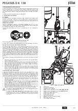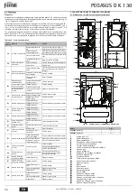
PEGASUS D K 130
34
EN
3.6 Connection to the flue
The flue connection pipe diameter must not be less than that of the connection on the
anti-backflow device. Starting from the anti-backflow device it must have a vertical sec-
tion at least 50 cm long. Comply with the current standards regarding installation and siz-
es of the flues and connection pipe.
The diameter of the anti-backflow device collar is given in fig. 25.
4. SERVICE AND MAINTENANCE
4.1 Adjustments
All adjustment and conversion operations must be carried out by Qualified Personnel.
The manufacturer declines any liability for damage and/or injury caused by unqualified
and unauthorised persons tampering with the unit.
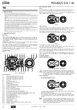
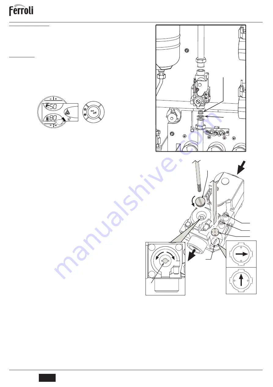
TEST mode activation
Press the
heating buttons
(details 3 and 4 - fig. 1) together for 5 seconds to activate the
TEST
mode. The boiler switches on irrespective of the system or DHW request.
The heating symbol (detail 24 - fig. 1) and DHW symbol (detail 12 - fig. 1) flash on the
display.
fig. 17 - TEST mode
To deactivate the Test mode, repeat the activation sequence.
The TEST mode is automatically disabled in any case after 15 minutes.
Heating system output adjustment
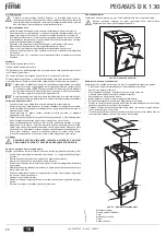
On PEGASUS D K 130 boilers, the firebox heating power and therefore the heat output
delivered to the heating water can only be adjusted by means of the main burner through
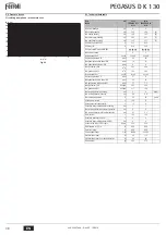
the gas valve, (see fig. 19). The diagrams given in the section cap. 5.2 indicate the var-
iation in heat output delivered to the water according to the change in burner operating
pressure. Being able to adjust boiler output to the actual heating requirements means
above all reducing heat losses, and therefore obtaining fuel saving. Also, with the varia-
tion in output, also regulated by the provisions, the boilers keep their efficiency levels and
combustion characteristics practically unchanged
This operation is carried out with the boiler working and the water storage tank heated.
1.
Using a small screwdriver, remove the secondary operator protection cap 5 of the
gas valve of fig. 19.
2.
Connect a manometer to the pressure point 2 (fig. 19) located below the gas valve,
and turn the boiler thermostat knob to the maximum value.
3.
Adjust the pressure to the required value by means of the screw 6 (fig. 19), referring
to the diagrams given in section cap. 5.2.
4.
Then turn the burner on and off 2 or 3 times by means of the control thermostat and
check that the pressure value is that just set; otherwise, another adjustment must
be made to bring the pressure to the correct value.
Gas conversion
The unit can work with Natural gas (G20-G25) or liquefied gas (G30-G31) and is factory-
set for use with one of the two gases, as clearly shown on the packing and dataplate.
Whenever a different gas to that for which the unit is arranged has to be used, the special
conversion kit will be required, proceeding as follows:
1.
Replace the nozzles at the main burner and pilot burner, fitting the nozzles specified
in the technical data table on cap. 5.3, according to the type of gas used.
2.
Remove the small protection cap
3
(fig. 19) from the gas valve. Using a small screw-
driver, adjust the ignition “STEP” for the required gas (
G20-G25
position
D
fig. 19),
or
G30-G31
position
E
fig. 19); then refit the cap.
3.
Adjust the gas pressure at the burner, setting the values given in the technical data
table for the type of gas used.
4.
Apply the sticker contained in the conversion kit, near the dataplate as proof of the
conversion.
B
To convert the boiler from
Natural Gas to LPG
, the gas diaphragm placed be-
tween the valve and the manifold pipe (ref. 7 - fig. 18) must be removed.
To convert the boiler from
LPG to Natural Gas
, the gas diaphragm and respec-
tive seal (ref. 7 and 8 - fig. 18) must be inserted. The correct gas diaphragm for
each boiler model is given in the technical data table on sec. 5.3.
fig. 18 - Gas diaphragm
fig. 19 - Pressure adjustment
A
Gas valve
B
Decrease pressure
C
Increase pressure
D
Ignition “STEP” adjustment for
G20-G25 NATURAL
gas
E
Ignition step adjustment for
G30-G31 LIQUEFIED
gas
F
Electronic controller
1
Pressure point upstream
2
Pressure point downstream
3
Protection cap
4
Ignition STEP regulator
5
Protection cap
6
Pressure adjustment screw
eco
comfort
m
o
d
e
r e s et
eco
bar
7
8
MIN
MAX
MIN
MAX
5
C
B
6
A
D
E
1
2
3
4
cod. 3540T644 - Rev. 0
-
/201
Summary of Contents for PEGASUS D 45 K 130
Page 78: ......
Page 79: ......
Page 80: ...FERROLI S p A Via Ritonda 78 a 37047 San Bonifacio Verona ITALY www ferroli it...


