background image

PEGASUS D K 130

19

ES

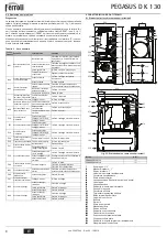
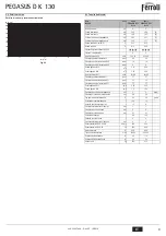
5.2 Pérdidas de carga
Pérdidas de carga / altura manométrica bombas de circulación

fig. 26

5.3 Tabla de datos técnicos

0

1

2

3

4

5

6

7

0

0.5

1

1.5

2

 Q 

[m

3

/h]

[m H

2

O]

3

1

2

2.5

3

Dato

Unidad

Valor

Valor

Modelo

PEGASUS D 30 

K 130

PEGASUS D 40 

K 130

Número elementos

kW

4

5

Capacidad térmica máxima

kW

32,2

42,9

(Q)

Capacidad térmica mínima

kW

14,9

19,7

(Q)

Potencia térmica máx. en calefacción

kW

30,2

40,1

(P)

Potencia térmica mín. en calefacción

kW

13,5

17,7

(P)

Rendimiento Pmáx (60-80 °C)

%

93,7

93,5

Rendimiento 30%

%

91,8

92,5

Clase de eficiencia según directiva 92/42 CE

Clase de emisión NOx

2

2

Inyectores quemador G20

nº x Ø

3 x 2,60

4 x 2,60

Presión de alimentación gas G20

mbar

20

20

Presión máx. en el quemador con G20

mbar

16

16

Presión mín. en el quemador con G20

mbar

4

4

Caudal máximo de gas G20

m

3

/h

3,41

4,54

Caudal mínimo de gas G20

m

3

/h

1,58

2,08

Inyectores quemador G31

nº x Ø

3 x 1,65

4 x 1,65

Presión de alimentación gas G31

mbar

37

37

Presión máx. en el quemador con G31

mbar

35

35

Presión mín. en el quemador con G31

mbar

7,7

7,7

Caudal máximo de gas G31

kg/h

2,52

3,36

Caudal mínimo de gas G31

kg/h

1,17

1,54

Presión máxima de funcionamiento en calefacción

bar

6

6

(PMS)

Presión mínima de funcionamiento en calefacción

bar

0,8

0,8

Temperatura máxima agua calefacción

°C

95

95

(tmáx)

Contenido del circuito de calefacción

L

12,5

15

Capacidad vaso expansión calef.

L

12

12

Presión de precarga vaso expans. calef.

bar

1

1

Presión máxima de funcionamiento en ACS

bar

9

9

Presión mínima de funcionamiento en ACS

bar

0,1

0,1

Contenido de agua sanitaria

L

130

130

Capacidad vaso de expansión ACS

L

4

4

Presión de precarga vaso expans. ACS

bar

3

3

Caudal de agua sanitaria 

'

t 30 °C l/10 min

l/10 min

250

250

Caudal de agua sanitaria 

'

t 30 °C l/h

l/h

850

850

Grado de protección

IP

X0D

X0D

Tensión de alimentación

V/Hz

230/50

230/50

Potencia eléctrica absorbida

W

110

110

Potencia eléctrica absorbida en ACS

W

90

90

Peso sin carga

kg

250

275

cod. 3540T644  -  Rev. 0

 - 

/201

Summary of Contents for PEGASUS D 45 K 130

Page 1: ...UCCIONES DE USO INSTALACI N Y MANTENIMIENTO TR KULLANMA KURULUM VE BAK M TALIMATLAR EN INSTRUCTIONS FOR USE INSTALLATION AND MAINTENANCE FR INSTRUCTIONS D UTILISATION D INSTALLATION ET D ENTRETIEN GR...

Page 2: ...temperatura impianto riscaldamento 5 Display 6 Tasto selezione modalit Estate Inverno 7 Tasto selezione modalit Economy Comfort 8 Tasto Ripristino 9 Tasto accensione spegnimento apparecchio 10 Tasto m...

Page 3: ...atura ambien te richiesta Per quanto riguarda il funzionamento con cronocomando remoto fare riferimento al relativo manuale d uso Temperatura scorrevole Quando viene installata la sonda esterna opzion...

Page 4: ...nisce una garanzia che assicuri che i suoi prodotti sono idonei all uso e non arrecano danni allo scambiatore di caldaia o ad altri componenti e o materiali di caldaia ed impianto proibito l uso di li...

Page 5: ...otare la manopola del termostato caldaia sul valore massimo 3 Regolare la pressione a mezzo della vite 6 fig 19 al valore desiderato avvalendo si dei diagrammi riportati al paragrafo cap 5 2 4 Termina...

Page 6: ...e corrisponda a quello indicato nella tabella dati tecnici al cap 5 3 Controllare che vi sia la giusta portata d acqua sanitaria con il t dichiarato in tabella dati tecnici non fidarsi di misure effet...

Page 7: ...ituata in un punto pi alto rispet to ai radiatori la parte di impianto comprendente questi ultimi dovr essere svuotata separatamente Per svuotare solamente l acqua contenuta nella caldaia chiudere le...

Page 8: ...acqua nell impianto Verificare il circolatore Presenza aria nell impianto Sfiatare l impianto F04 Intervento del termostato fumi dopo l intervento del termostato fumi il funziona mento della caldaia v...

Page 9: ...1 58 2 08 Ugelli bruciatore G31 n x 3x1 65 4x1 65 Pressione gas alimentazione G31 mbar 37 37 Pressione gas max al bruciatore G31 mbar 35 35 Pressione gas min al bruciatore G31 mbar 7 7 7 7 Portata ga...

Page 10: ...Termostato fumi 130 Circolatore bollitore 138 Sonda esterna 139 Unit ambiente 246 Trasduttore di pressione 278 Sensore doppio Sicurezza Riscaldamento DSP05 7 6 5 4 3 2 1 11 10 9 8 7 6 5 4 3 2 1 T1 T2...

Page 11: ...portatenelpresenteCer cato Gliinterven ingaranzianon modi cano la data di decorrenza della garanzia e non prolungano la durata della stessa Esclusioni Sono esclusi dalla presente garanzia i dife di co...

Page 12: ...S 12 S mbolo de agua caliente sanitaria 13 Indicaci n de funcionamiento en ACS 14 Ajuste temperatura de salida ACS 15 Indicaci n de modo Eco Economy o Comfort 16 Temperatura sensor exterior con sonda...

Page 13: ...a ambiente requerida Por lo que se refiere al funcionamiento con el reloj pro gramador a distancia consultar su manual de uso Temperatura adaptable Si est instalada la sonda externa opcional en la pan...

Page 14: ...caldera ni ning n otro componente o material del aparato o de la instalaci n Se proh be usar l quidos anticongelantes aditivos e inhi bidores gen ricos que no est n expresamente indicados para el uso...

Page 15: ...si n 2 fig 19 situada despu s de la v l vula del gas y poner el mando del termostato de la caldera en el valor m ximo 3 Regular la presi n por medio del tornillo 6 fig 19 en el valor deseado gui ndose...

Page 16: ...que el consumo de gas indicado en el contador corresponda al indica do en la tabla de los datos t cnicos del cap 5 3 Controlar que el caudal de agua sanitaria sea correcto con el t indicado en la tabl...

Page 17: ...alaci n que comprende los radiadores se tiene que vaciar por separado Para vaciar nicamente la caldera cerrar las v lvulas de paso y abrir la llave 255 fig 25 A continuaci n desbloquear los obturadore...

Page 18: ...a en la instalaci n Controlar la bomba de circulaci n Aire en la instalaci n Purgar de aire la instalaci n F04 Actuaci n del termostato de humos tras la cual la caldera queda bloqueada durante 20 segu...

Page 19: ...G31 n x 3 x 1 65 4 x 1 65 Presi n de alimentaci n gas G31 mbar 37 37 Presi n m x en el quemador con G31 mbar 35 35 Presi n m n en el quemador con G31 mbar 7 7 7 7 Caudal m ximo de gas G31 kg h 2 52 3...

Page 20: ...ostato de humos 130 Bomba de circulaci n acumulador 138 Sonda externa 139 Unidad de ambiente 246 Transductor de presi n 278 Sensor doble calefacci n seguridad DSP05 7 6 5 4 3 2 1 11 10 9 8 7 6 5 4 3 2...

Page 21: ...la cumplimentaci n de la totalidad de los datos en el Certi cado de Funcionamiento La cumplimenta ci n del certi cado deber realizarse inmediatamente a la P M y consignar la fecha correctamente envi...

Page 22: ...nomi Konfor modu se im tu u 8 Resetleme tu u 9 Cihaz al t rma kapatma tu u 10 S cakl k Ak men s tu u 11 Ayarlanan s cak s hhi su s cakl na ula ld n belirten g sterim 12 S cak s hhi su sembol 13 S cak...

Page 23: ...ktan kumandal zamanlay c kontrol ile ilgili daha fazla bilgi i in l tfen bu cihaz n kullan c kitab na bak n z S cakl k ak Harici sens r n monte edilmesi opsiyonel ile kumanda paneli g sterge ekran nda...

Page 24: ...vermeyece ini garanti ediyorsa izin verilebi lir Is tma sistemlerinde kullan mlar n n uygun oldu u ve kombi nitesi ile sistemlerinin aksamlar ile uyumlu oldu u a k a beyan edilmeyen normal s radan ant...

Page 25: ...3 Vida 6 ek 19 arac l yla cap 5 2 paragraf nda yer alan diyagramlardan yararla narak bas nc talep edilen de ere gelecek ekilde ayarlay n z 4 Bu i lemden sonra ayarlama termostat arac l yla br l r 2 3...

Page 26: ...inin cap 5 3 b l m ndeki tek nik veriler tablosunda verilen de er ile ayn oldu undan emin olunuz S cak su kapasite de erinin do ru ve teknik veriler tablosunda belirtilen t ile ayn oldu undan emin olu...

Page 27: ...rumda sistemin radyat rleri i eren k sm ayr olarak bo alt lmal d r Sadece kombi i erisindeki suyu bo altmak i in a ma kapama valflar n kapat n z ve muslu u tamamen kapat n z 255 ek 25 Akabinde geri d...

Page 28: ...ombinin al mas 20 dakikal na durdurulur Duman termostat n n konta a kt r Termostat kontrol ediniz Kablolarda kopukluk var Kablo tesisat n kontrol ediniz Bacan n ebatlar yanl t r veya t kal durumdad r...

Page 29: ...r G31 n x 3x1 65 4x1 65 Gaz besleme bas nc G31 mbar 37 37 Br l r maksimum gaz bas nc G31 mbar 35 35 Br l r minimum gaz bas nc G31 mbar 7 7 7 7 Maks gaz k G31 Kg s 2 52 3 36 Min gaz k G31 Kg s 1 17 1 5...

Page 30: ...Duman termostat 130 Kazan sirk lat r 138 Harici sens r 139 Ortam nitesi 246 Bas n d r c 278 ift sens r Emniyet Is tma DSP05 7 6 5 4 3 2 1 11 10 9 8 7 6 5 4 3 2 1 T1 T2 X7 7 6 5 4 3 2 1 6 5 4 3 2 1 X5...

Page 31: ...on 7 Economy Comfort mode selection button 8 Reset button 9 Unit On Off button 10 Sliding Temperature menu button 11 Set DHW temperature reached 12 DHW symbol 13 DHW mode 14 DHW outlet temperature set...

Page 32: ...ature For information on the remote timer control please refer to its user s manual Sliding temperature When the optional external probe is installed the control panel display detail 5 fig 1 shows the...

Page 33: ...he heat exchanger or other components and or materials of the boiler unit and sys tem It is prohibited to use generic antifreeze fluid additives or inhibitors that are not ex pressly suited for use in...

Page 34: ...e pressure point 2 fig 19 located below the gas valve and turn the boiler thermostat knob to the maximum value 3 Adjust the pressure to the required value by means of the screw 6 fig 19 referring to t...

Page 35: ...on the meter matches that given in the technical data table on cap 5 3 Check the correct flow of domestic hot water with the t given in the technical data table do not trust measurements made with emp...

Page 36: ...er is located higher than the radiators the part of the system in cluding the radiators must be drained separately To drain just the water contained in the boiler close the shutoff valves and fully op...

Page 37: ...positioning and operation of the heating sensor No water circulation in the system Check the circulating pump Air in the system Vent the system F04 Fume thermostat activated after activation of the f...

Page 38: ...1 no x 3x1 65 4x1 65 Gas supply pressure G31 mbar 37 37 Max gas pressure at the burner G31 mbar 35 35 Min gas pressure at the burner G31 mbar 7 7 7 7 Max gas delivery G31 4 22 kg h 2 52 3 36 Min gas d...

Page 39: ...mostat 130 Hot water tank circulating pump 138 External probe 139 Room unit 246 Pressure transducer 278 Double sensor Safety Heating DSP05 7 6 5 4 3 2 1 11 10 9 8 7 6 5 4 3 2 1 T1 T2 X7 7 6 5 4 3 2 1...

Page 40: ...he de s lection du mode t Hiver 7 Touche de s lection du mode Eco Confort 8 Touche de remise z ro 9 Touche de Marche Arr t de l appareil on off 10 Touche du menu Temp rature volutive mode 11 Indicatio...

Page 41: ...eau de l instal lation en fonction de la temp rature ambiante demand e Pour le fonctionnement par chronocommande distance se reporter au manuel d utilisation sp cifique Temp rature volutive Lorsqu une...

Page 42: ...sont idoines l utilisation et ne provoquent pas de dommages l changeur de la chaudi re ou d autres com posants et ou mat riaux de la chaudi re et de l installation Il est interdit d utiliser des liqu...

Page 43: ...mont e en aval de la vanne gaz tourner le bouton du thermostat de la chaudi re sur la position maximum 3 R gler la pression l aide de la vis 6 fig 19 sur la valeur d sir e conform ment aux diagrammes...

Page 44: ...tableau des caract ristiques techniques cap 5 3 Contr ler que le d bit d eau chaude sanitaire correspond celui du t indiqu sur le tableau des caract ristiques techniques ne pas se fier des mesures emp...

Page 45: ...s par ment Pour vider uniquement l eau contenue dans la chaudi re fermer les vannes d arr t et ouvrir compl tement le robinet 255 fig 25 D bloquer ensuite les obturateurs des clapets anti retour 179...

Page 46: ...d eau dans l installation V rifier le circulateur Pr sence d air dans l installation Purger l installation F04 D clenchement du thermostat s curit fum es apr s son d clen chement le fonctionne ment d...

Page 47: ...ini au br leur G25 mbar 5 5 D bit gaz puissance maxi G25 m h 3 96 5 28 D bit gaz puissance mini G25 m h 1 83 2 42 Gicleurs br leur G31 nbre x 3 x 1 65 4 x 1 65 Pression d alimentation gaz G31 mbar 37...

Page 48: ...n 126 Thermostat fum es 130 Circulateur ballon 138 Sonde ext rieure 139 Unit ambiante 246 Transducteur de pression 278 Capteur double s curit chauffage DSP05 7 6 5 4 3 2 1 11 10 9 8 7 6 5 4 3 2 1 T1 T...

Page 49: ...HUR RLNLDN 9 FU VK9 12 6 PEROR HVWR QHUR RLNLDN 9 FU VK9 13 QGHL K OHLWRXUJ D9 QHUR RLNLDN 9 FU VK9 14 5 TPLVK THUPRNUDV D H GRX HVWR QHUR RLNLDN 9 FU VK9 15 QGHL K OHLWRXUJ D9 Eco Economy Comfort 16...

Page 50: ...HUPRNUDV D WDQ J QHWDL HJNDW VWDVK HQ 9 H ZWHULNR DLVTKW UD SURDLUHWLN VWKQ RT QK WRX S QDND FHLUL VPR H UW 5 fig 1 HPIDQ HWDL K WU FRXVD H ZWHULN THUPRNUDV D V PIZQD PH WK P WUKVK WRX H ZWHULNR DLVTK...

Page 51: ...9 VWRQ HQDOO NWK WRX O EKWD VH OOD H DUW PDWD NDL XOLN WRX O EKWD NDL WK9 HJNDW VWDVK9 SDJRUH HWDL K FU VK DQWL XNWLN Q XJU Q SURVTHWLN Q NDL DQDVWRO ZQ JHQLN 9 FU VK9 WDQ GHQ DQDI UHWDL UKW WL H QDL...

Page 52: ...IOH K9 WRSRTHW QWD9 WD PSHN SRX XSRGHLNQ RQWDL VWKQ SLQDN GD WHFQLN Q VWRLFH ZQ cap 5 3 DQDO JZ9 WK9 WXSRORJ D9 WRX FUKVLPRSRLR PHQRX DHU RX 2 IDLU VWH DS WK EDOE GD DHU RX WR PLNU NDS NL SURVWDV D9 3...

Page 53: ...T UPDQVK9 NDL WL K SDUDJZJ QH UR RLNLDN 9 FU VK9 H QDL RPDO 4 3 6XQW UKVK B 2 3 5 7 5 6 6 35 3 1 7 2817 32 67 0212 32 80 12 7 57 60 12 3526 3 2 fig 24 1 bar QRLJPD PSURVWLQR S QDND LD QD DQR HWH WRQ...

Page 54: ...VH VF VK PH WD NDORULI U WR WP PD WK9 HJNDW VWDVK9 PH WD NDORULI U SU SHL QD HNNHQZTH H FZULVW LD HNN QZVK P QR WRX QHUR WRX O EKWD NOH VWH WL9 EDOE GH9 GLDNRS 9 NDL DQR WH SO UZ9 WK VWU ILJJD 255 fi...

Page 55: ...WKQ HJND W VWDVK DHU VWH WKQ HJNDW VWDVK F04 QHUJRSR KVK THUPRVW WK NDXVDHU ZQ PHW WKQ HQHU JRSR KVK WRX THUPRVW WK NDXVDHU ZQ R O EKWD9 W THWDL HNW 9 OHLWRXUJ D9 JLD 20 OHSW QRLNW HSDI THUPRVW WK NDX...

Page 56: ...mbar 37 37 0 JLVWK S HVK DHU RX VWRQ NDXVW UD G31 mbar 35 35 O FLVWK S HVK DHU RX VWRQ NDXVW UD G31 mbar 7 7 7 7 0 JLVWK SDURF DHU RX G31 kg h 2 52 3 36 O FLVWK SDURF DHU RX G31 kg h 1 17 1 54 0 JLVW...

Page 57: ...4HUPRVW WK9 NDXVDHU ZQ 130 XNORIRUKW 9 PS LOHU 138 ZWHULN 9 DLVTKW UD9 139 0RQ GD F URX 246 0HWDOO NWK9 S HVK9 278 LSO 9 DLVTKW UD9 DVIDOH D9 T UPDQVK9 DSP05 7 6 5 4 3 2 1 11 10 9 8 7 6 5 4 3 2 1 T1...

Page 58: ...n ingestelde temperatuur verwarmingsinstallatie 5 Display 6 Keuzetoets modus Zomer Winter 7 Keuzetoets modus Economy Comfort 8 Resettoets 9 Toets in uitschakelen apparaat 10 Toets menu Weersafhankelij...

Page 59: ...grond van de gewenste omgevingstemperatuur Voor wat de werking met timerafstand sbediening betreft wordt verwezen naar de betreffende gebruikershandleiding Weersafhankelijke temperatuur Wanneer de ex...

Page 60: ...wisselaar of aan overige componenten en of materialen van verwarmingsketel en installatie Het is verboden antivriesmiddelen additieven en rem mende stoffen te gebruiken die bestemd zijn voor algemene...

Page 61: ...n de gasklep van fig 19 2 Sluit een manometer aan op de drukaansluiting 2 fig 19 benedenstrooms van de gasklep en draai de thermostaatknop van de verwarmingsketel op de maximale waarde 3 Stel de druk...

Page 62: ...angegeven in de tabel met de technische gegevens in cap 5 3 Controleer of de toevoer van sanitair water juist is en overeenkomt met t van de tabel technische gegevens neem geen genoegen met metingen u...

Page 63: ...etel zich op een hoger gelegen punt dan de radiatoren bevindt moet het gedeelte van de in stallatie waartoe deze behoren afzonderlijk afgetapt worden Om alleen het water in de verwarmingsketel af te t...

Page 64: ...latie Controleer de circulatiepomp Lucht in de installatie Ontlucht de installatie F04 Ingrijpen van de rookther mostaat na het ingrijpen van de rookthermostaat wordt de werking van de verwarmingskete...

Page 65: ...3 h 1 58 2 08 Sproeiers brander G31 n x 3x1 65 4x1 65 Gasdruk voeding G31 mbar 37 37 Max gasdruk bij de brander G31 mbar 35 35 Min gasdruk bij de brander G31 mbar 7 7 7 7 Max gasdebiet G31 kg uur 2 52...

Page 66: ...mostaat 130 Circulatiepomp boiler 138 Buitentemperatuursonde 139 Omgevingseenheid 246 Drukomzetter 278 Dubbele sensor Beveiliging Verwarming DSP05 7 6 5 4 3 2 1 11 10 9 8 7 6 5 4 3 2 1 T1 T2 X7 7 6 5...

Page 67: ...Comfort 12 13 1 Comfort 15 1 11 1 3 conomy COMFORT 15 1 ECO 15 1 ECO eco comfort 7 1 7 1 2 3 4 B sez 3 3 5 120 FH 5 FH A A01 15 RESET eco comfort m o d e r e s e t ecomfort bar 5 7 9 10 2 1 8 6 4 3 1...

Page 68: ...eco comfort m o d e r e s e t eco comfort m o d e r e s e t eco bar eco comfort m o d e r e s e t eco bar eco comfort m o d e r e s e t eco bar eco comfort m o d e r e s e t eco bar 20 30 40 50 60 70...

Page 69: ...A 1 5 1 1 1 0 F37 15 15 A 120 FH 3 3 1 3 2 A 3 3 B cap 5 1 25 Fr 1 F 10 CaCO3 15 F 236 88 B 6 C 3 4 B 25 B 3 5 B Y 3 3A 2 B HAR H05 VV F 3x0 75 2 8 B 230 A 16 ECO COMFORT Eco nomy 7 1 Comfort 7 1 A A...

Page 70: ...SUS D K 130 19 cap 5 2 1 5 19 2 2 19 3 6 19 cap 5 2 4 2 3 G20 G25 G30 G31 1 cap 5 3 2 3 19 G20 G25 D 19 G30 G31 E 19 3 4 B 7 18 7 8 18 sez 5 3 18 19 A B C D G20 G25 E G30 G31 F 1 2 3 4 5 6 eco comfort...

Page 71: ...PEGASUS D K 130 71 RU 4 2 B 1 19 120 FH 5 FH A A01 15 RESET A cap 5 3 t 4 3 B 24 1 20 B 20 21 21 1 2 3 4 5 6 1 2 4 3 2 1 5 6 cod 3540T644 Rev 0 201...

Page 72: ...PEGASUS D K 130 72 RU 2 3 6 21 4 21 20 233 25 275 25 179 25 22 255 25 179 25 197 25 A 179 25 22 A B A D B 23 C A 23 24 1 2 3 4 5 6 7 8 A B A B B D C cod 3540T644 Rev 0 201...

Page 73: ...255 273 275 293 A01 A02 A03 F04 20 A06 F10 1 F11 F14 2 F34 170 F35 F37 F39 F40 A41 F42 F47 A48 A49 A i PEGASUS D 30 K 130 131 PEGASUS D 40 K 130 151 A 40 44 255 273 74 180 197 246 32 130 293 143 178 9...

Page 74: ...1 8 92 5 92 42 EEC NOx 2 2 G20 x 3 x 2 60 4 x 2 60 G20 20 20 G20 16 16 G20 4 4 G20 3 3 41 4 54 G20 3 1 58 2 08 G31 x 3x1 65 4x1 65 G31 37 37 G31 35 35 G31 7 7 7 7 G31 2 52 3 36 G31 1 17 1 54 6 6 PMS 0...

Page 75: ...46 278 DSP05 7 6 5 4 3 2 1 11 10 9 8 7 6 5 4 3 2 1 T1 T2 X7 7 6 5 4 3 2 1 6 5 4 3 2 1 X5 F1 F2 X1 X2 X4 X3 X6 X8 X10 2 1 T T 278 GND 5V OUT 246 L N 230V 50Hz 138 139 72 L N 4 5 6 7 8 9 10 11 12 13 14...

Page 76: ...42 Direttiva Rendimenti 92 42 Direttiva Bassa Tensione Direttiva Compatibilit Elettromagnetica IT Declaration of conformity Manufacturer FERROLI S p A Address Via Ritonda 78 a 37047 San Bonifacio VR I...

Page 77: ...lijn Rendementseisen 92 42 EEG Laagspanningsrichtlijn Richtlijn Elektromagnetische compatibiliteit FERROLI S p A Via Ritonda 78 a 37047 San Bonifacio VR O 2009 142 O 92 42 O T O H NL D claration de co...

Page 78: ......

Page 79: ......

Page 80: ...FERROLI S p A Via Ritonda 78 a 37047 San Bonifacio Verona ITALY www ferroli it...

Reviews: