


OPTIMAX HE 31 S
18
Cod. 3540F441 - 03/2007 (Rev. 01)
Pitch roof slate
1KWMA82U
1KWMA56U
950
50
1KWMA71W
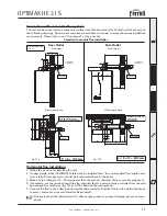
max. 6 mt 60/100
max. 16 mt 80/125
Vertical Terminal
1KWMA83U
68
950
50
50
950
50
1000
125
10
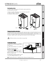
eco
comfort
reset
1
2
3
4
0
BAR
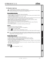
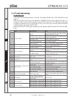
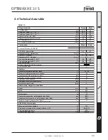
Vertical Outlet
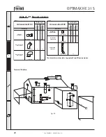
fig. 17c
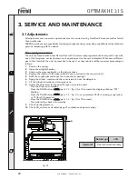
Reduction factors for bends
1 m
0,5 m
0,5 m
0,25 m
Table 2b
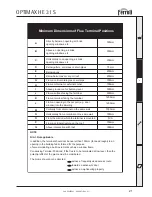
Maximum permissible
duct length (Horizontal)
Ø mm
60/100
5 m
15 m
Ø mm
80/125
Table 2a
Maximum permissible
duct length (Vertical)
6 m
16 m
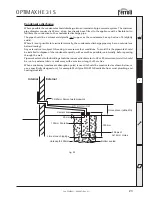
The total length in equivalent metres of the concentric flue must not exceed the maximum lengths stated
in the following table, note that each bend gives rise to the stated reduction. For example, a duct = 60/100
composed of 1 bend of 90° +1 horizontal metre + 2 bends of 45° + 1 horizontal metre has a total equivalent
length of 4 metres.
Vertical flueing
The installation of a concentric vertical flue can be carried out as follows,
Install the appliance as previously mentioned in this manual.
1.
Connect onto the flue assembly at the top of the appliance a concentric vertical adaptor part number
1KWMA71W,
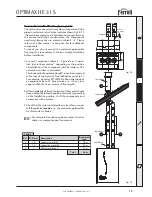
2.
Use the required amount of 1mtr flue extensions (part number 1KWMA56U) inserting them spigot
down ensuring the seals are well lubricated with silicone grease (not supplied) and correctly located
into the sockets.
3.
If required 45° bends (Part number1KWMA64A)
may be used with a resistance value of 0.5mtrs
each, the flue should be routed in such away
to avoid any unnecessary deviation and thus
minimise the amount of bends required.
4.
The termination should be made through our
concentric flue outlet (part number 1KWMA83U)
in conjunction with a roof slate pitched (part
number 1KWMA82U) or flat roof (part number
1KWMA81U) The storm collar must be fixed on
using the three screws provided and sealed with
an external grade silicone (not supplied).
5.
For longer flue lengths a 125mm concentric flue
system is available.
6.
All flue installations must comply with BS5440
part 1 and must only be of Fèrroli manufacture.
The vertical flue must continually rise and be
supported throughout its length. The flue must
be inspected whilst commissioning the appliance
to ensure it is sound throughout its length.
This information is for guidance purposes and Fèr-
roli will in no way be held responsible for incorrect
installation following this guide.
Summary of Contents for OPTIMAX HE 31 S
Page 36: ......